Welcome to David and Janet Ribbans blog

We live in Adelaide, South Australia and enjoy travel in the Australian outback in our Oka 4WD motorhome, hence the blog title.


To quickly locate any of our more than 80 travel and technical articles, use the drop down menus below or scroll down the lists in the right hand sidebar. But please read the disclaimer first, we've tried to be accurate and current but things can change...
You can also visit the official Oka 4WD website here.

Pandora Web Archive


We're now honoured to have our blogs archived
on the National Library of Australia's Pandora Web Archive.
Bookmark this link to the archived version in case anything ever goes wrong with Google, or I accidentally hit "Delete All" in a fit of pique. The drop down menus above might not work in the archived version but everything else should...

Sunday, 16 March 2008

How to add Power Windows to an Oka

IMG_1431.JPG-2008-03-16-07-21.jpg

This blog describes how I added power windows to our Oka.

Since the Oka front door windows are belt driven, very heavy and different to other cars, I thought that fitting power windows would be difficult, if not impossible, but it wasn't impossible.

There are no doubt other ways to do it (there are many American websites selling power window lifters, or regulators as they call them, of many different types for all manner of vehicles, but not Oka of course), but this way was quite simple and effective.

I bought a 2 door power window kit from Rapid Electronics in Melbourne via ebay for $95 plus $20 shipping. There are other suppliers and types available as well but the kits are not available all the time. However they reappear regularly for around the same price. Delivery was very quick and most kits seem to use the same rectangular silver drive motors now, which are claimed to be "high power", which is encouraging.

How do they work?

To see how they work, visit these sites. Installation Guide #1 and Installation Guide #2.

OK, so they are shown being fitted to an old Holden, but the principles and operation are the same, and they show far more detail than I was intending to.

I have not yet determined the longevity of the motors and drive assemblies on an Oka, but on short term testing they seemed OK, even though the motors do take a fair whack of current (10+ Amps, over 120 watts, when closing the windows) and get pretty hot.

Fitting them to an Oka

To fit them to an Oka means the following operations:
  • Remove the door handles, grab handles and window winders from both front doors.
  • Remove the christmas tree fixings and remove the plastic trim
  • At some stage you'll probably want to remove the door stays too, either to be able to open the doors further or when they get in the way.
Since the Oka windows are pretty heavy at the best of times, you'll need to lighten the load as much as possible by:
  • Releasing the tension on the friction slide mechanism.
  • Greasing the window slide channels on both sides and the belt slide channel. I used lithium grease but there may well be better products for this purpose.
The window should wind up and down freely using the original window winder, if not, the electric motor drive will have a tough job closing the windows.

I used to have the slide friction pads tightened up as much as possible to stop the windows from sliding down and rattling on rough roads. With the electric version, the worm drive on the motor unit should prevent the motor from being turned by the window and keep it tightly shut. We'll see.

[Post trip note: Yes, the worm drive DID prevent the windows from rattling or sliding down. This was after a 14,000 km outback trek including the Anne Beadell Highway, Great Central and Sandy Blight Junction Roads.]

Locating the Motor Drive Assembly

Fitting the power window motor assembly took some trial and error. I tried 3 or 4 different locations:
  • Option 1: In the well above the grab handles, or in the cut out near the door catch.
IMG_1391.JPG-2008-03-16-07-21.jpg

In the well didn't work out since the motor, although thin, is too fat and fouled the door trim and/or the window glass, although the belt is nice and straight. In the cut out near the door catch would have worked fairly well with the belt skirting around the bottom of the door handle bracket.
  • Option 2: In the space just above the floor but below the door trim.
This would have worked mechanically but would protruded into the cabin and would have needed a cover made.


IMG_1390.JPG-2008-03-16-07-21.jpg

  • Option 3: In the cut out near the door hinges.
IMG_1393.JPG-2008-03-16-07-21.jpg

I thought this would foul the window glass when wound down but it didn't, and proved to be the most suitable location.

The door trim fits back almost perfectly, except for a slight bulge where it goes over the drive belt beneath the door stay. This is almost unnoticeable.

The motor drive belt is designed to be bent around as long as the centres of the motor and drive cog are not less than 30o mm apart. In this configuration they end up about 400 mm apart.
  • Option 4: I have power door locks fitted to our Oka, bits of which fill up the other cut out near the door catch, otherwise that area might have been a possibility too, with the belt skirting beneath the door handle bracket. Fitting the cables from here would be more difficult.
Mounting the Motor Drive Assembly

Mounting the motor drive assembly and securing the drive belt cog is not difficult with the items supplied, just a bit of cutting, bending, drilling and screwing. Most of the other bits in the kit are intended for use in cars where the noise and vibration of the motor might be distracting. Not a critical Oka concern.

I fitted a piece of rubber sheeting between the motor body and the door skin too avoid any scuffing or noise as the motor vibrates. It's no noisier than a normal car power window.

The drive belt will foul the body of the door stay slightly as the door closes, so a small strap was fitted to pull the belt closer to the door skin and out of the way of the door stay.

If you locate the drive motor here, drill the 12mm cable hole in the door through the cutout before mounting the motor.

Assembling the Drive Mechanism

Assembling the drive cog on the window winder was also easy, at first.

A large number of different cogs, gears and spacers are provided in the kit to suit different cars. We don't need any of them.

With the window winder removed, the shortest of the large nylon cogs fits neatly over the splined shaft, and the drive belt cog from the motor slips over the nylon cog to drive the window winder up and down. In theory.

Having assembled the cogs and mounted the motor and drive belt, I hooked up a 12v source and tried it out. It worked reasonably well on the drivers door, but when I tried it on the passenger door, a problem arose. Over the years, the tops of the splines had worn down so when the window reached the top and stopped, the power of the motor continued to turn the drive cog which slipped around, wearing off the peaks of the nylon cog on the worn down steel splines. If this didn't happen now, it was certainly going to happen sometime soon, so another approach was needed.

Soft nylon turning a steel splined shaft at high torque is not a good match. What was needed was a mechanical locking method to tie the splined shaft to the nylon drive cog. (I figured that there was less torque on the teeth of the larger drive belt cog from the motor (twice as big, therefore a 1/4 of the torque??) and so it was going to last longer, so I focused on the smaller cog).


IMG_1394.JPG-2008-03-16-07-21.jpg


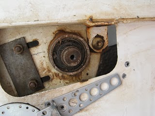
First I removed the splined shaft from the window winder mechanism by releasing the (quite strong) circlip holding it in and removing the plastic spacer and shaft. It was easier than I though it would be.
(Note: When replacing it, ensure that the ends of the internal spring are correctly located in the shaft cut-out.)

Then I made a round steel plate the size of the nylon cog (and so the end of the drive belt opening would slip over it) and drilled a 5mm clearance hole in the centre. (The original window winder handle is held on to the splined shaft by a 5mm bolt).

I drilled a series of 2mm holes in the plate, 4 around a small circle which coincided with the end of the splined shaft, and 4 which coincided with the ring of the nylon cog. I then fitted the nylon cog to the splined shaft and cut it down flush with the end of the splined shaft.


IMG_1403.JPG-2008-03-16-07-21.jpg


After mounting the plate on the splined shaft with a 5mm bolt, I drilled through the holes in the plate using a 2mm drill, into the end of the splined shaft to a depth of 6mm, and right through the nylon cog.

This is best done on a pedestal drill for stability and accuracy and after drilling the first hole, drop a 2mm bolt in it to stop the plate from rotating while the others are drilled.

Mark the plate and shaft so that it can be replaced in the same orientation, unless you can achieve perfection in drilling accuracy.


IMG_1408.JPG-2008-03-16-07-21.jpg


Having made one plate that fits, it's a good idea to use it as a template for the others and drill them before cutting and rounding the plates. It makes them easier to handle.

They don't actually have to be round, square or octagonal would do, so long as the drive belt cog can fit over it and there is room for the 2mm bolts. Round just seemed a neater solution. There was no need for nuts on the 2mm bolts (there's no space anyway) as I held all the bolt heads in place with another round plate, via a clearance hole in its centre, with a 5mm bolt. Like a sandwich. A blob of Selleys All Clear on the bolt threads would reduce any movement as well.

Using 2mm bolts, (6mm long into the shaft and 8-10mm long through the nylon cog), I assembled the plate to the splined shaft.


IMG_1412.JPG-2008-03-16-07-21.jpg

pbp-2008-03-16-07-21.gif
A blob of Selleys All Clear on the bolt threads would reduce any movement as well.


IMG_1415.JPG-2008-03-16-07-21.jpg


The whole assembly is now mechanically locked together with the 8 x 2mm bolts acting as locking pins.

The plates were painted to avoid corrosion before final fitment, as were the holes drilled in the door skin.

Once the system is operating satisfactorily, I shall Loctite the 5mm bolt in place to avoid anything coming loose.

2mm bolts are not the only way of achieving this fix, roll pins or any small steel pins would do, but bolts with heads on are more easily held in position and they do need to be small, there is not a lot of room to move. Small self tappers might also work but they would probably come loose. 3mm bolts might just fit but would be trickier to position accurately.

2mm nuts and bolts are available from Dick Smith and Jaycar Electronics.


IMG_1405.JPG-2008-03-16-07-21.jpg


4 bolts on each section are probably a bit of an overkill, but it looks symmetrical and strong, and works well.

When the mechanism is fitted finally, there is thin spring/circlip supplied in the kit which must be slipped over the larger nylon cog into a groove, to tie it to the drive belt cog, otherwise it could slide off while operating.

I found in practice that the thin spring came adrift during operation, and I couldn't see any way that the drive belt cog could slip off, it's held on pretty tight by the mounting brackets, so it's probably not essential.

With this mechanical locking system in place, when the window gets to the top, the mechanism now stops with no slipping. However, in this position the motor is stalled and will be drawing maximum current, so it must not be held there for more than a second or so to avoid overheating (and eventual burn out) of the motor. You would hope that the motor design takes account of this situation with a thermal cutout or similar, but how can we be certain?

Originally I was intending to leave the window winder in place to enable some manual assistance to be provided to raise the window if the system struggles, or in the event of a failure to the system. However this is not practical since if the system fails though an electrical fault (eg a blown fuse or burnt out motor, a likely cause with heavy windows), the torque from the worm drive on the motor shaft would prevent the window winder from operating, and with my mechanical shaft locking in place, it can't be easily fitted on anyway. So in the event of either electrical or mechanical failure, the mechanism would have to be removed and the original winder assembly replaced. (Note to self: Mustn't forget to take them with us on our next trip).

Wiring the Electrics

The kit comes with a cable harness and 2 switch assemblies, a double switch for the drivers door to operate the windows on both doors, and a single switch for the passenger door.

Switch housings are provided which can be screwed to the door trim from the inside in the most comfortable position. Alternatively, the switches could be mounted directly in rectangular cutouts in the door trim, if the housings take up too much space. However, there might not be sufficient space behind them for the cables in that orientation.

Cables will need to be fed though the frame of the door and the Oka body to allow connections to be made to the motors and switch assemblies. This will require 12mm or 1/2 inch holes, with grommets to protect the wires.

Drill a hole in the end of the door first through the cutout where the motor will be mounted. A corresponding hole is required in the Oka body about 75mm lower (or higher) than in the door, to provide room for the cables to twist without straining as the door opens and closes.

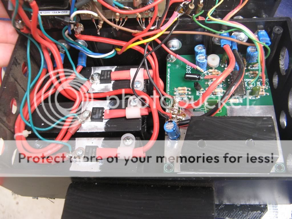
I was not convinced that the cables supplied would be man enough for the job, especially when raising the passenger window from the drivers side. The wires carry quite high currents across the vehicle and require to be fairly meaty cables.

The main culprits are the White, Blue and Blue/Red cables running across from the drivers door switch to the passenger door motor. They carry the full motor current when raising and lowering the passenger window across all the way from the drivers side, even when the passenger door switch is operated. The positive current to the passengers door is supplied by the White wire which is spliced into the Red wire, which is the primary +12v supply. With the original cables, I was losing about 4 volts across the cables during winding (12v down to around 8-9v across the motor connections). This is far too much and caused the motors to struggle.

The best fix is to replace the full length of the Blue, Blue/Red and White wires with much heavier cables (or put additional cables in parallel to share the load). Also the Red and Black supply wires should also be heavier. Lastly the Pink and Yellow wires to the motors can be made heavier and shorter once the switch and motor positions are finalised. This way the losses are reduced to less that 2 volts. Not perfect but acceptable.

[Post Trek Note: Yes the wiring to the solenoids DOES need to be as thick and direct as possible. The window motors will struggle if the battery voltage is low or the window slides are sticky with dust, especially the passengers side, where the cables are longest.

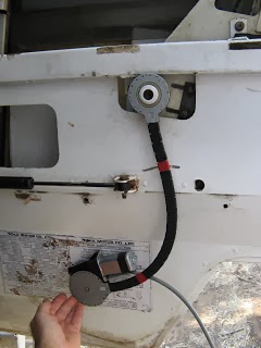
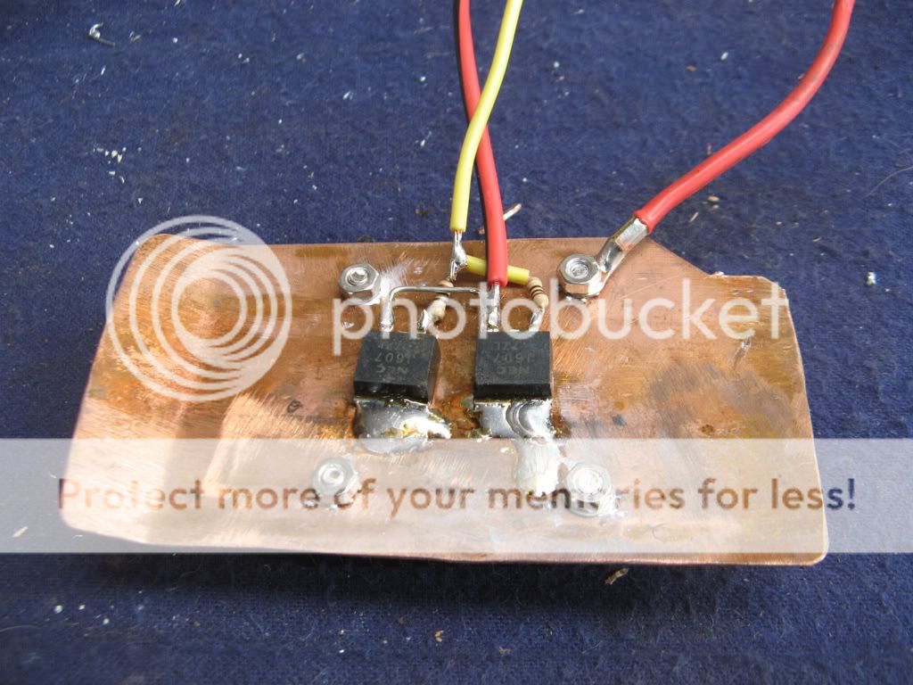
I have subsequently fitted a heavy current earth cable direct into the passenger door (along the door stay from it's mounting bolt) and used 2 relays, driven from the existing wires from the drivers door switch, to operate the passenger side motor. This works much better and reduced the voltage loss to around 1 volt, since it avoids the need for heavy earth currents to run across the vehicle to the drivers side switch and thence to ground.


Passenger%25252BSide%25252BRelay%25252BMod-2008-03-16-07-21.jpg

The relays are normal auto relays but need to be SPDT models having both NO (87A) and NC (87) terminals (eg Dick Smith P8035). Most relays are SPST models with only a single ON/OFF contact connection. We need the changeover function for the system to work.


IMG_0975.JPG-2008-03-16-07-21.jpg

The relays squeezed in along side the motor. They are mounted on an aluminium plate, offset to ensure there is sufficient clearance with the window glass. Note the gooseneck on the black ground cable from the door strut to allow it to move as the door opens and closes.

You should also check that there is a good earth connection between the main vehicle chassis frame (which the battery ground is strapped to) and the body/cab frame, which is mounted on rubber insulating mountings. If in doubt, bolt a short earth strap between the 2 frames, it will help with other electrical problems too.

Also leave the friction pads slightly touching (but not impeding) the glass, otherwise the glass can slip forward and jam in its tracks].

The system will need a good earth connection and a heavy current connection to the positive battery terminal, preferably direct, not via the ignition switch, so windows can be operated with the engine off. Under the instrument binnacle (in an XT) there is a white 4 way connector which carries the ignition supply to and from the steering column ignition switch. The Orange wire on the left is a heavy current source from the battery and is a good place to tap into the 12v supply. You can clearly see where I have amateurishly tapped in before.


IMG_1417.JPG-2008-03-16-07-21.jpg


I had previously had problems with the white connector overheating, when the airconditioning was on full fan, and burning the connectors which were presumably higher resistance than they should be. So I have replaced the connector with 4 new heavy duty spade terminals. This enables me to tap into the Orange wire (which connects to the Brown wire from the steering column!) using a 2 way spade connector.

If you don't want the window to be operated unless the ignition is on, connect to the Pink wire (on the left, which connects to the White wire from the steering column), or to operate in the Accessories and Ignition positions, use the Brown wire (on the left, which connects to the White/Green wire from the steering column). Don't use the Purple wire (which connects to the White/Red from the steering column), since this only powers the start solenoid.

Just to add to the confusion, on the Oka wiring diagram, the Purple and Brown wires are not shown. Instead it refers to the Violet commoned with White/Red, Pink, Orange and White/Green. I've drawn a colour coded connection diagram for my own benefit showing the Signal Name, the colour of the wire actually fitted in our Oka, the wire colours as shown in the Oka manual, and the wire colours inside the steering column. Your wiring maybe different.


Oka%25252BIgnition%25252BWiring-2008-03-16-07-21.jpg


Note, in the Accessories position, quite a lot of power is being used even if nothing appears to be on. A whole load of relays are powered up under the dashboard, just in case, so it's not a good idea to leave the ignition switch in the accessories position, unless you are actually using something, like the radio or a/c fans. Ironically, most driving functions, like lights, horn, wipers and indicators, operate without the ignition being on at all.

There was no obvious solid ground point under the instrument binnacle for the black wire so I took the ground cable out though the front with the steering column cables and used one of the steering column anchor bolts as a ground connection. [Another option is to use the mounting bolt for the fixed end of the door stabiliser strut as a ground point and run a thick black wire along the strut and into the door cavity, ensuring that there is enough slack to allow the door to open fully.]

Choose carefully the location for the switches on the door trim. On the drivers side, there are the steering column and wiper control stalk to consider. I found the most comfortable position on both sides was directly above the existing window winder opening, lower on the drivers side to avoid interfering with the wiper stalk, but higher on the passenger side to avoid it hitting his or her leg. In these positions the cables will fit into the switch module from inside, and above, the horizontal bar under the window ledge. Drill holes as necessary to anchor cables with tie-wraps to avoid them interfering with the window glass as it moves.

Completing the Job

Various size covers are provided in the kit to cover the hole left by the original window winder. You may need to bore out the plastic trim to fit them, or cut them down to size and glue them on. (Or paint a smiley face on the end plate and leave it showing though the hole in the door trim).

When refitting the plastic trim it may be necessary to cut it to fit around the drive belt and motor area, or put up with a slight bulge as I have done.

Once the handles are all back in place you would hardly know that the door now hides a power window system.

Although I haven't done this yet , it is possible to fit a remote control to raise and lower the windows remotely if needed, or when the vehicle is left and locked up, for example. A timer, or better still, a "window up" sensor, would be required so that the window drive motor is not operating for too long. Alternatively, Rapid Electronics sell a Window Lifter module to do just that, for $39. It would need to be wired to the Orange battery wire so that this function can operate without the ignition key in place.

Fitting Solar Panels to an Oka

I have fitted 10 x 20 Watt Solar Panels to our Oka (5 panels across the front and a further 5 panels recently fitted in a strip down the left of the roof).
(Click on photos for a larger view.)

I chose this route rather than buying single 60-80 watt panels for the following reasons:
  • If one fails or gets broken, it's easier and cheaper to replace, and the others will continue to operate in the meantime.
  • Since they are wired in parallel, if one or more is shaded, the others will continue to produce their full output.
  • Separate panels are easier to mount in different locations and/or orientations for maximum benefit.
  • 5 x SP20 panels (in a package deal from Oatley Electronics, Melbourne, now superseded by these 3 larger panels) were no more expensive than a single Unisolar 64 watt panel.
I have also fitted a solar regulator, charge current monitor and blocking diode system to enable 3 batteries to be charged from one regulator.

[Post Trip Note: During a 14,000 km trek in June-Sept 2008 across outback tracks in SA, WA and the NT, the solar panel system performed extremely well. It took quite a bit of effort and experimenting to remember park for the night so that the solar array would gain maximum benefit from next morning's sun during the 7-9 am period. We would normally park in the afternoon for maximum shade, which is not necessarily the most effective for next morning's sun. It wasn't as intuitive as I thought it would be to get the bearings right for the morning sun and also avoid shade from overhanging obstacles. But when we got it right, it really helped replenish the previous evening's use of power before starting out. The scrub bars fitted to the sides of the array proved invaluable in deflecting branches on tight overgrown desert tracks like the Anne Beadell. Periodic washing the dust off the panels also helped their efficient significantly.]

Because we built a raised roof on our Oka, the solar panel frame I have constructed to fit over the cab will be different to that required by other Oka configurations. However, the mechanical and electrical design principles would remain essentially the same.

The frame is constructed from 25 mm square aluminium tube and braced across all corners and joints. I have also incorporated scrub bars along the edges to deflect tree branches away from the panels.


The panels are tilted at approx. 15º, partly to collect sunlight when facing north and partly to force cooling airflow over and under the panels when moving. When we are parked, we always face the vehicle north into the sun so the rear compartment is shaded, and put a sun screen across the windscreen to keep the heat out of the cab. This minimises the solar heating effect in the rear of the motorhome and neatly matches the needs of the solar panels. We also have reflective screens for all the rear compartment windows, made from Aircell insulation, from Bunnings.

The solar panels are grouped across a curved frame, which follows the contours of the roof line. Using a curved frame also provides some stiffening of the cross members. The addition of subsequent solar panels will be in lines along both sides of the rear roof.
The frame is supported on arms which are bolted to the roof rack mounting points and are braced to the top of the sun visor to provide front and rear stability.

[Post Trip Note: Ensure that there are no panel edges or lips protruding beyond the scrub bars as they will get knocked and bent by passing branches. This will loosen or break pop rivets and weaken the structure. Where this is likely, or if it happens on the road (as it did to us), replace the pop rivets with 5 or 6 mm bolts and Nyloc nuts.]

Mechanical Construction

I used 3 lengths of 25mm tube bent 3º at 4 locations so that each panel could rest on a flat section.
On the top and lower cross bars, I fitted a 50mm wide strip of 2mm aluminium, curved to the contour of the cross bar. This provides 2 benefits:
  • Stiffening of the cross bar and resistance to bending, and
  • A 20mm lip on the outer sides of the top and lower bar for the solar panels to slot into and be bolted to.
The centre bar is to support the centres of the panels if they have any tendency to bend.

The side supports are also bent inwards to fit the side contour of the Oka and to minimise the overall width of the frame. Alongside the panels, and continuing down to the sun visor, are more 25mm tubes to provide bracing and also deflection of tree branches.
All the joints were fixed with 6mm pop rivets, and the whole frame was painted white to keep it as cool as possible.
Holes were drilled in the end frames of the solar panels and corresponding holes made in the lips of the end plates of the frame. The panels were attached with 5mm nuts and Nyloc bolts. I also put a layer of foam under the panels to dampen any vibrations.

The panels weigh around 2.5 kgs each and the all up weight of the frame plus panels is around 15 kgs, which is not an excessive mass for mounting above the cab.

The additional 5 panels are mounted in an aluminium track frame which is attached to the left hand roof line. The track is made of 3mm thick 25mm aluminium angle with cross bracing straps between every 2 panels. To reduce flexing during assembly and mounting, stiffening straps were attached to the sides of the frame where the panels met.

Bespoke brackets were made to hold the track about 15mm from the the roof, aligned to the ribbed beams of the roof frame. The beams are 25 mm aluminium tubes so even though penetrations were required to mount the frame (using galvanised Tek screws), they don't go right through the roof and any water that does get in will run down the inside of the tubes and into the side gutters. I sealed the brackets and fixing screws with silicon to minimise water ingress and to prevent the screws from working loose.

Test fitting the frame to the roof
The panels being fitted to the frame before painting.


They are electrically connected in parallel with the front panels and use the same regulator system which can handle up to 15 amps of charge.

Post fitting note:

While fitting the new panels I noticed that one of the front panels was broken. It had been hit by a rock or other sharp object, but it must have happened some time ago because the point of impact was stained with red outback dust. Being made of toughened glass, it had crystallised into hundreds of pieces but none had fallen out and it still felt quite solid.

The broken solar panel which still works fine


I did consider removing the panel and replacing the glass or maybe the whole panel but I found that it was still working pretty much as well as all the others, and it's not that easy to remove a panel with the frame up in the air, so it will stay in place for the time being. (I checked by shading some panels individually and monitoring the effect on the charge rate).
It does, however, justify my original decision to use several smaller panels rather that a couple of larger ones. The score is now Windscreens 2 : Solar panels 1.
I am wondering now if a sheet of clear polycarbonate would protect the remaining panels without cutting down their efficiency too much, and if the point of impact could be sealed with clear epoxy (eg Selleys Araldite Ultra Clear).

Electrical Connections


Each of the panels has a small junction box attached to the rear. I removed the covers and refitted thicker wires to minimise power losses, since those provided were fairly short and flimsy, and in one case was not adequately soldered to the panel connector.


The current from each panel is relatively small (1.3 amp max.) so the wires can be daisy chained across the frame using crimp connectors and a single red/black pair taken down to the cab for distribution to the batteries. The cables were run down inside one of the support legs of the frame to avoid damage due to passing flora.
Underneath view of the solar panel array

  
To provide some current monitoring, I connected a third thin wire (brown actually) to the negative wire at the junction of the last panel. This is used by a sensitive electronic circuit to sense the voltage drop along the negative wire and to display the approximate curent flowing through it. It will only be around 50 mV at full current, but that is sufficient to measure.

In the cab, I have mounted a solar regulator unit (part of the Oatley kit, which requires some detailed electronics skills to construct) and a current monitor circuit and display. The current monitor is not essential to the system but the solar regulator certainly is.
Solar panels generate over 20 volts when open circuit in full sunlight, and develop maximum current (just over 1 Amp per panel in this case) at about 17 volts. This is more than enough to damage electronic equipment, so solar panels must never be attached directly to electronic equipment or batteries without some form of regulator.

The Oatley K009E regulator, see this link, monitors the state of the battery attached to it and turns on a power MOSFET to charge the battery. When the battery is fully charged or disconnected, the circuit is switched off to avoid over charging.

The solar charge controller and its charge display
The current monitor I used was derived from a car alternator charge monitor, see this link, adjusted to show only a positive display (since no current can flow back through the panels).


If you have only a single battery, or only want the solar panels to charge one battery, the output from the regulator can be connected directly to the battery. If you have more than one battery, the situation is slightly more complex.

To charge 2 or more batteries, they have to be connected together. This is fine while they are being charged since they will all take a charging current proportional to their state of charge, assuming they are all of a compatible type. However, when they are not being charged, during darkness for example, one will have a slightly higher terminal voltage than the others and will discharge into the other batteries, leading, in the worst case, to a flat battery within a few hours, or at the very least some power being wasted. Also, with batteries in parallel any load will be supplied from any or all them, which might not be what is intended, and a discharged starter battery might result. To prevent this from happening, a blocking diode must be inserted in series with each battery lead from the solar regulator. These should be low voltage drop, 20 Amp Schottky power diodes, which are quite cheap and easy to get, see this link. I also fitted switches in series with each battery lead so I can direct the charge to whichever batteries need it most.

[In a future mod, I'll replace the Schottky diodes with power MOSFETs since they have a very low ON resistance and there will be a lower voltage drop across them and therefore minimal power loss. Although I will need to consider the parasitic reverse diode built in to all MOSFETs].

There is a slight complication in regard to the Oatley regulator however, as it requires to monitor the battery voltage to determine whether it should switch on or not. With blocking diodes in the circuit it can't do that, and so it won't switch on. I have therefore connected 2.2k resistors across each of the blocking diodes to enable the regulator to monitor the battery voltage. This works fine and does not provide a serious discharge path between batteries. A maximum of around 5 mA can flow between batteries which is a trivial amount.

[Post Trip Note: We also have a 120A alternator plus a Stirling Smart Alternator Regulator (AR12VD) which charges the batteries using a 3 stage process while driving. This works well, but since I fitted solar panels I found that there could be some interaction between the 2 systems. Solar charging can confuse the alternator regulator, leading it to think the batteries are fully charged when they are not, and reduce the charging current accordingly.
I now turn off solar charging whilst driving and turn it on only when parked. This will be automated in future so the solar system turns on only when the alternator (ie engine) is off. (Ironically, re-reading Collyn Rivers book "Motorhome Electrics" after several years, this is exactly what he recommends, pp 39-40).
The alternative would be to separate the house batteries which the solar panels charge, from the alternator charging system and starter battery, but this doesn't make sense, unless you have a very large solar panel set up, as the alternator can always provide far more charge than solar panels could ever do. In any case, the Oka always uses 2 batteries during normal operation, the starter and auxiliary batteries, and separating those might engender other problems.
While the solar system is not performing the duties of main battery charging (such as when the alternator is charging the batteries), it can put to use for other purposes. I use it to charge my cordless drill batteries which requires more than 20v to charge the 15.6v battery, which is exactly what the solar array can develop, or it can be used to operate any other devices which require, or can withstand, more than 12v (ie a 12-24v input range). You could drive a cordless drill direct from solar panels if its battery fails. Note that the solar panel output voltage can vary wildly over the range from 0 to 24v or more due to shading or cloud cover to bright sunlight, so read the instructions carefully!].

Monitoring the output from the solar panel array
Testing Phase


Testing a solar panel array means:
  • Having a flatish battery to charge, and
  • Working in the hot sun, it can't be done indoors or at night.
I put my array in the front garden in full sun and connected it to the battery in my ride-on lawn mower, which is always neglected.
I was able to measure a maximum of around 6 amps from the array (1.2A per panel, which is around their specified maximum output) and an average over several hours of 4-5 amps as the sun transversed the sky, which is quite acceptable.

Testing the solar pane array
This is not the 100 watts advertised however, since it is never possible to extract the theoretical maximum from solar panels, but 70-80 watts over 8+ hours equates to around 40 amp-hours per day. This provides sufficient power for the domestic requirements of a caravan or motorhome, or to recharge a severely discharged battery, eg. in the event of an alternator failure or overuse of the computer system!
Now we have duplicated the solar panel array, these figures have roughly doubled and a continuous 10-12 amps can be easily obtained in full sun.


Solar Regulator Failure

During our Cape York trip, the solar regulator failed. This was caused by the higher current being generated by the new 200 W array.

The current is controlled by a power MOSFET soldered to the rear of the regulator circuit board, which contains a small heat sink.

The MOSFET was mounted under the PCB where the brown patch is
This heat sink is fine for 120 W but inadequate to control 200 W and at some time the MOSFET got so hot that its solder melted and it slid down the circuit board.


The MOSFET has overheated causing the solder to melt and it slid down the board
I couldn't replace it at the time so I rigged up a temporary arrangement using some transistors and a standard automotive relay to take its place. This worked fine for the rest of the trip.


When we arrived home, I replaced the failed MOSFET by a pair of MOSFETs connected in parallel, and mounted on an external heatsink. This comprised a piece of copper plate adapted from some old kitchen utensils from a second hand shop and a small PC CPU heatsink.

I used a small heat shunt to prevent the MOSFETs from overheating as I soldered their tabs using a small gas torch.


I used a small gas blow torch to solder the MOSFETs since the copper sheet absorbs so much heat
A PC CPU heat sink bolted to the rear of the panel
The new assembly was rewired in alongside the original PCB vertically to allow cooling air to pass over it.

New heatsink fied alongside the circuit board in the vertical airflow

This new arrangement works fine and should be capable of controlling up to 400 W of solar panels if more are added in the future.

Monday, 24 December 2007

Tracks we've been on and our thoughts... (under construction)

Tracks we've been on and what we thought.
All these tracks should be considered as 4WD only, although some may be possible in a sturdy high clearance 2WD. Check carefully first.
Limited fuel and water supplies on all these tracks and some require permits.
Queensland
Sandover Highway Mount Isa to Alice SpringsEasy, deep to moderate sand and gravel on the NT section. No facilities but quite scenic. Tricky to find the start at the QLD end. 800 kms.
Bloomfield Track. Cooktown to Cape TribulationDifficult, steep winding and slippery gravel. Drainage channels along the sides so there's not much room for error. Despite the track being along the coast, there almost no views of the sea due to the dense vegetation.
Cape York Peninsular Development Road
Cairns to the Tip
Fairly easy (some corrugations) using bypass tracks NOT the OTT, long, hot and dusty (need lights on).
$88 ferry return fare (trailers extra) at Jardine River crossing.
Plenty of side trips (Weipa, Mapoon, Pennefather River (deep sand!), Capt Billy Landing, Chilli Beach, Portland Roads, Lochhart River). Very windy on east coast, calm on the west. Regular road houses.
Bamaga, Seisia, Somerset at the tip. Take a trip to Thursday Island. Lakefield National Park and Cooktown on return.
800 kms plus side trips.
South Australia
Googs Track. Ceduna to Tarcoola.Great fun and not too difficult. Deep sand and plenty of sand dunes. Camping at Googs Lakes and Mount Finke. 200 kms. Permit needed. South to North direction recommended. Use CB and sand flags on crests.
Western Australia
CSRWe've done 2/3rds of the CSR in 2 stages, comprising the top section from Bililuna to Well 33 near Kunawaritji (700 kms), and the centre section from Well 33 to Georgia Bore near Well 22 (300 kms). The CSR is long and lonely but a great desert experience and well worth all the the effort and planning. It covers hundred of sand dunes, some of which are a bit difficult. However, once you start, there is almost no chance of vehicle recovery except under it's own steam, so total self sufficiency is a prerequisite. No permit required unless you deviate off the track but access tracks will require permits.
Gary HighwayVery corrugated but quite easy. No facilities. (400 kms from Kunawaritji to Everard Junction, plus another 400 kms to Warburton). Veevers Crater and McPhersons Pillar are worth investigation. See my Wiki entry at http://en.wikipedia.org/wiki/Gary_Highway.
Eagle HighwayVery variable, narrow and very overgrown in places, the track is almost indicernable and poses a navigation hazard, May large washaway's needing diversions. No facilities. (800 kms from Great Central Road to Kunawaritji via the Talawana Track and CSR).
Talawana TrackVery corrugated but quite easy. No facilities except good water at Midway Well. (200 kms from Eagle Highway Junction to the CSR near Well 24).
Kidson TrackThis track used to be a very challenging 4wd track from Kunawaritji (Well 33 on the CSR) to 80 Mile beach. During 2012, much of the western end of the track was graded to allow access for mining vehicles and has become a wide smooth gravel road. The eastern 200km still has demanding sand dunes and overgrown section. 650kms, no facilities.
Parmango Road
Balladonia to Condingup (Cape Arid)
This is a useful shortcut (in distance, not time) between Balladonia and Cape Arid (Condingup township, store/fuel). 200 km, wide track but rough in the Balladonia section, better at the southern end. Would be difficult in the wet. Sign at northern end restricts vehicles to 4WD and 3Tonnes. No signs at the southern end and unnecessary anyway. Be aware that the Mt Ragged alternative route to Cape Arid (turns off half way along) may be narrow and impassable after rain and Esperance is a very wet area.
Steep Point
Shark Bay to the most westerly point of the Australian mainland
This track starts as a fairly smooth gravel road (120km) on the Useless Loop road from Hamlyn Pool on Shark Bay via Tamala Station. (Note the gravel used is salt residue from the salt works and will become quite corrosive when wet. Wash down the underside of your vehicle if returning after rain). It then deteriorates as you approach the Steep Point National Park where it becomes a difficult, narrow sandy track (40km) across several challenging sand dunes to the Ranger Station. 
Nuytsland Nature Reserve
Track due south from Madura
This track south starts just east of Madura as a fairly smooth 10km gravel road to Madura Cave which is worth a visit.  Thereafter, it deteriorates into a narrow sandy and overgrown track for a further 40km towards the coast. Although narrow, it is navigable with care over soft sand dunes dodging the low slung vegetation. This track does not actually reach the coast, the bush become impenetrable and it terminates at a track junction a km from the beach, but is is quiet and very scenic with plenty of birdlife. There are a few secluded camping areas along the track and at the junction. The beach could be reached on foot (which we didn't do, it felt scarily remote), as there are signs of earlier now overgrown tracks further south.
Northern
Territory
Tanami Track. Halls Creek to Alice SpringsLong gravel track (1100 kms) but not too difficult. Reasonable facilities along the way. Rabbit Flat Roadhouse is no longer operating and this can catch people out if you need fuel half way along but Yuendumu and Tilmouth Well road houses are open. No facilities at the Granite Goldmine.
SA-WA
Anne Beadell Highway. Coober Pedy to LavertonVery long (1500 kms), fairly straight but very corrugated. No water on SA side, fuel and 3 water tanks on WA side. Good desert scenery plus a section of sandhills. Items of interest: Atomic bomb sites, Emu Field and Dingo Claypan. Aircraft wreck. Several permits needed.
WA-NT
Gary Junction Road. Alice Springs to NewmanLong straight and easy track which passes some historic outback locations: Sandy Blight Junction, Talawana, Gary Highway Junction, CSR, Rudall River National Park. Good camping at Jupiter Well. (1500 kms Alice to Newman). Permits needed.
Sandy Blight Junction RoadWinding and tortuous but interesting (400 kms and longer than expected). Deep corrugated sand alternating with rocky gravel. Interesting scenery on the southern section. Permit needed.
Tasmania
Road to Nowhere. Stanley to Strachan.This is an interesting winding track down the western side of Tassie. Depending on the season it can be cold, wet and cloudy or misty but there is plenty of vegetation, water features, coastal access and green hills. The surface is gravel which can be slippery, but the steep hilly sections are bitumen. There is a ferry at Corinna across the Pieman River. Beware of leeches on the damp vegetation. (300 kms)
Oodnadata Track. Maree to Marla or Painted DesertFairly easy (except when wet) and full of interesting locations: Mound Springs, Old Ghan Railway Line, Plane Henge Sculpture Park, Lake Eyre, Old Peake Telegraph Station, Painted Desert (west from Oodnadata), Dalhousie Springs and Mount Dare (to the north east of Oodnadatta). (600 kms)
NT-SA
Old Andado Track. Alice Springs to OodnadataNice remote red sand dune country. Old Andado Station is worth a visit for a cup of tea. Access to Dalhousie Hot Springs which are good for swimming, even in winter (100 m long lake with water at 38º) (400 kms)
WA-QLD
Great Central RoadEasy going but not very inspiring. The road now bypasses all the native wells along the way, which is disappointing. Giles Met Office is well worth a visit. (1000 kms from Laverton to Yulara, +/- a couple). Permit required.
Plenty HighwayFairly easy track but the QLD end is not well marked or maintained. (6-7oo kms depending where you end up in QLD)
NT
Mareenie Loop roadVery scenic road from Kings Canyon to Hermansberg, but very corrugated in parts. (200 kms). Permit needed.
WA-NT
Gibb River RoadA bit rough in places but this is more than made up for by the many scenic gorges, water falls and rivers along the way. (650 kms excluding Mitchell Falls, which is another 600 kms round trip from the Gibb River Road junction, see below).
Mitchell Falls RoadVery corrugated track but leads to the beautiful Mitchell falls so it's worth the suffering. Good camping at Drysdale Station, King Edward River and at the falls. Extra trek to Surveyors pool is worthwhile on a newly made but re-aligned track, which now starts further north than marked on maps. Access to Port Warender (no facilities) is also possible but the track is VERY steep and tortuous towards the end. (600 kms return from Gibb River Road junction including Surveyors Pool).
QLD-SABirdsville Track Easy but wide, rocky desert track. Nice mirages when it's hot and sunny. Can be very dusty. (300 kms)

Wednesday, 5 December 2007

Outback Signs

When traveling the outback you will always come across signs, some funny, some sad, some rude, some informative and some which, well, just don't seem to make much sense.

Here are a selection we've come across (including a few we found on the web but are still relevant).

Although not a sign (but maybe symbolic?), this is an interesting (and maybe fake?) mud pool in the shape of Oz. (From the web)

A funny but meaningful sign from FNQ. (From the web)

Berribee State Forest, only something's missing.

Here you could see the wood for the trees, if there were some.

The Dingo fence near Coober Pedy.

300 Mile Peg at Dingo Claypan. 300 miles down range from the Woomera Rocket Range launch pad.

Original Len Beadell sign, LWRE 1951, at the 300 mile peg at Dingo Claypan.

Radiation warning sign at Emu Field says "Don't Raise Dust". Duh!

Aboriginal radiation warning sign at Emu Field. Presumably you can catch kangaroos but not camp.

Vokes (or Voakes?) Hill Sign on the Anne Beadell Highway.

Atomic Bomb Tests, Camera C Site at Emu Field.

Culturally Sensitive Area on the Anne Beadell Highway.

Unnamed Conservation Park on the Anne Beadell Highway.

Neale Junction on the Anne Beadell Highway. 1000 km from Coober Pedy and 400 km to Laverton.

Aircraft Wreck sign on the Anne Beadell Highway.

Laverton That-A-Way Blokes, at the western end of the Anne Beadell Highway.

Lake Ballard

Warburton Fuel Pumps, where taking photos is not allowed.

Sea Level marker at Giles Met Office, to 1 cm accuracy.

200 Mile rock, on the Sandy Blight Junction Road.

Highest Point Cairn on the Stuart Highway. The plaque provides every possible detail except how high it actually is. (730 m apparently, someone's added it in Texta).

Stuart's "Presumed S" tree at Daly Waters.

Heritage Sign at Fenton Air Base. Sad return for a WW11 veteran.

No feeding Kangaroos sign at Lawn Hill.

Daly Waters Parking "restrictions".

Doomagee Beer "Limit", on Highway 1 in the Gulf.

Boulia Shire 1 and 2 signs, very detailed and comprehensive.

Min-Min Light at Boulia.

Shoe Tree on the Birdsville Track

Somewhat unnecessary sign on the Birdsville Track

Camp Paradise? I think not, on the Great Central Road.

Walk Wade or Swim to the Manning Falls on the Gibb River Road.

Shire of where? On the Great Central Road.

Lift Um Foot, on the Mareenie Loop Road.

Puttum Back Down, on the Mareenie Loop Road.

Desert Queen Baths junction marker in the Rudall River National Park.

Indie Station Gate, near Port Hedland.

Road Kill Cafe in Darwin at Mindil Markets.

Outback Sign on CSR, too easy to miss.

Toilet Seat road junction sign on the CSR which leads to Separation Well.

Veevers Meteorite Crater off the Gary Highway.

Are we there yet? On the Mitchell Falls Road.

Shockie Grove, on the CSR

Spring Gully, on the CSR

Grave sign made from a tin can, on the CSR

No kissing at Lawn Hill?

Igloos in Australia? At Cowell on the Eyre Peninsula.

Pointer to the Visitors Book (glass jar) hanging in a bush at McPhersons Pillar, 30 km east from the Gary Highway.

Water sign half way up a tree on the Gunbarrel Highway. Important not to miss signs like that.

There's important directional information buried in this sign on the Gunbarrel/Heather Highway junction.

Sign at the end of the McPhersons Pillar track, 30 kms from the Gary Highway.

A baby road-train. (From the web)

I wonder how many calls Todd gets? (From the web)