


(Click on photos for a larger view.)
I chose this route rather than buying single 60-80 watt panels for the following reasons:
- If one fails or gets broken, it's easier and cheaper to replace, and the others will continue to operate in the meantime.
- Since they are wired in parallel, if one or more is shaded, the others will continue to produce their full output.
- Separate panels are easier to mount in different locations and/or orientations for maximum benefit.
- 5 x SP20 panels (in a package deal from Oatley Electronics, Melbourne, now superseded by these 3 larger panels) were no more expensive than a single Unisolar 64 watt panel.
[Post Trip Note: During a 14,000 km trek in June-Sept 2008 across outback tracks in SA, WA and the NT, the solar panel system performed extremely well. It took quite a bit of effort and experimenting to remember park for the night so that the solar array would gain maximum benefit from next morning's sun during the 7-9 am period. We would normally park in the afternoon for maximum shade, which is not necessarily the most effective for next morning's sun. It wasn't as intuitive as I thought it would be to get the bearings right for the morning sun and also avoid shade from overhanging obstacles. But when we got it right, it really helped replenish the previous evening's use of power before starting out. The scrub bars fitted to the sides of the array proved invaluable in deflecting branches on tight overgrown desert tracks like the Anne Beadell. Periodic washing the dust off the panels also helped their efficient significantly.]

Because we built a raised roof on our Oka, the solar panel frame I have constructed to fit over the cab will be different to that required by other Oka configurations. However, the mechanical and electrical design principles would remain essentially the same.
The frame is constructed from 25 mm square aluminium tube and braced across all corners and joints. I have also incorporated scrub bars along the edges to deflect tree branches away from the panels.
The panels are tilted at approx. 15º, partly to collect sunlight when facing north and partly to force cooling airflow over and under the panels when moving. When we are parked, we always face the vehicle north into the sun so the rear compartment is shaded, and put a sun screen across the windscreen to keep the heat out of the cab. This minimises the solar heating effect in the rear of the motorhome and neatly matches the needs of the solar panels. We also have reflective screens for all the rear compartment windows, made from Aircell insulation, from Bunnings.
The solar panels are grouped across a curved frame, which follows the contours of the roof line. Using a curved frame also provides some stiffening of the cross members. The addition of subsequent solar panels will be in lines along both sides of the rear roof.
The frame is supported on arms which are bolted to the roof rack mounting points and are braced to the top of the sun visor to provide front and rear stability.
[Post Trip Note: Ensure that there are no panel edges or lips protruding beyond the scrub bars as they will get knocked and bent by passing branches. This will loosen or break pop rivets and weaken the structure. Where this is likely, or if it happens on the road (as it did to us), replace the pop rivets with 5 or 6 mm bolts and Nyloc nuts.]
Mechanical Construction
I used 3 lengths of 25mm tube bent 3º at 4 locations so that each panel could rest on a flat section.
On the top and lower cross bars, I fitted a 50mm wide strip of 2mm aluminium, curved to the contour of the cross bar. This provides 2 benefits:
- Stiffening of the cross bar and resistance to bending, and
- A 20mm lip on the outer sides of the top and lower bar for the solar panels to slot into and be bolted to.

The side supports are also bent inwards to fit the side contour of the Oka and to minimise the overall width of the frame. Alongside the panels, and continuing down to the sun visor, are more 25mm tubes to provide bracing and also deflection of tree branches.
All the joints were fixed with 6mm pop rivets, and the whole frame was painted white to keep it as cool as possible. 
Holes were drilled in the end frames of the solar panels and corresponding holes made in the lips of the end plates of the frame. The panels were attached with 5mm nuts and Nyloc bolts. I also put a layer of foam under the panels to dampen any vibrations.
The panels weigh around 2.5 kgs each and the all up weight of the frame plus panels is around 15 kgs, which is not an excessive mass for mounting above the cab.
The additional 5 panels are mounted in an aluminium track frame which is attached to the left hand roof line. The track is made of 3mm thick 25mm aluminium angle with cross bracing straps between every 2 panels. To reduce flexing during assembly and mounting, stiffening straps were attached to the sides of the frame where the panels met.
Bespoke brackets were made to hold the track about 15mm from the the roof, aligned to the ribbed beams of the roof frame. The beams are 25 mm aluminium tubes so even though penetrations were required to mount the frame (using galvanised Tek screws), they don't go right through the roof and any water that does get in will run down the inside of the tubes and into the side gutters. I sealed the brackets and fixing screws with silicon to minimise water ingress and to prevent the screws from working loose.

Test fitting the frame to the roof

The panels being fitted to the frame before painting.
They are electrically connected in parallel with the front panels and use the same regulator system which can handle up to 15 amps of charge.
Post fitting note:
While fitting the new panels I noticed that one of the front panels was broken. It had been hit by a rock or other sharp object, but it must have happened some time ago because the point of impact was stained with red outback dust. Being made of toughened glass, it had crystallised into hundreds of pieces but none had fallen out and it still felt quite solid.
 |
| The broken solar panel which still works fine |
I did consider removing the panel and replacing the glass or maybe the whole panel but I found that it was still working pretty much as well as all the others, and it's not that easy to remove a panel with the frame up in the air, so it will stay in place for the time being. (I checked by shading some panels individually and monitoring the effect on the charge rate).
It does, however, justify my original decision to use several smaller panels rather that a couple of larger ones. The score is now Windscreens 2 : Solar panels 1.
I am wondering now if a sheet of clear polycarbonate would protect the remaining panels without cutting down their efficiency too much, and if the point of impact could be sealed with clear epoxy (eg Selleys Araldite Ultra Clear).
Electrical Connections
Each of the panels has a small junction box attached to the rear. I removed the covers and refitted thicker wires to minimise power losses, since those provided were fairly short and flimsy, and in one case was not adequately soldered to the panel connector.
The current monitor I used was derived from a car alternator charge monitor, see this link, adjusted to show only a positive display (since no current can flow back through the panels).
Each of the panels has a small junction box attached to the rear. I removed the covers and refitted thicker wires to minimise power losses, since those provided were fairly short and flimsy, and in one case was not adequately soldered to the panel connector.
The current from each panel is relatively small (1.3 amp max.) so the wires can be daisy chained across the frame using crimp connectors and a single red/black pair taken down to the cab for distribution to the batteries. The cables were run down inside one of the support legs of the frame to avoid damage due to passing flora.
To provide some current monitoring, I connected a third thin wire (brown actually) to the negative wire at the junction of the last panel. This is used by a sensitive electronic circuit to sense the voltage drop along the negative wire and to display the approximate curent flowing through it. It will only be around 50 mV at full current, but that is sufficient to measure.
 |
| Underneath view of the solar panel array |
To provide some current monitoring, I connected a third thin wire (brown actually) to the negative wire at the junction of the last panel. This is used by a sensitive electronic circuit to sense the voltage drop along the negative wire and to display the approximate curent flowing through it. It will only be around 50 mV at full current, but that is sufficient to measure.
In the cab, I have mounted a solar regulator unit (part of the Oatley kit, which requires some detailed electronics skills to construct) and a current monitor circuit and display. The current monitor is not essential to the system but the solar regulator certainly is.
Solar panels generate over 20 volts when open circuit in full sunlight, and develop maximum current (just over 1 Amp per panel in this case) at about 17 volts. This is more than enough to damage electronic equipment, so solar panels must never be attached directly to electronic equipment or batteries without some form of regulator.
The Oatley K009E regulator, see this link, monitors the state of the battery attached to it and turns on a power MOSFET to charge the battery. When the battery is fully charged or disconnected, the circuit is switched off to avoid over charging.
 |
| The solar charge controller and its charge display |
If you have only a single battery, or only want the solar panels to charge one battery, the output from the regulator can be connected directly to the battery. If you have more than one battery, the situation is slightly more complex.
To charge 2 or more batteries, they have to be connected together. This is fine while they are being charged since they will all take a charging current proportional to their state of charge, assuming they are all of a compatible type. However, when they are not being charged, during darkness for example, one will have a slightly higher terminal voltage than the others and will discharge into the other batteries, leading, in the worst case, to a flat battery within a few hours, or at the very least some power being wasted. Also, with batteries in parallel any load will be supplied from any or all them, which might not be what is intended, and a discharged starter battery might result. To prevent this from happening, a blocking diode must be inserted in series with each battery lead from the solar regulator. These should be low voltage drop, 20 Amp Schottky power diodes, which are quite cheap and easy to get, see this link. I also fitted switches in series with each battery lead so I can direct the charge to whichever batteries need it most.
[In a future mod, I'll replace the Schottky diodes with power MOSFETs since they have a very low ON resistance and there will be a lower voltage drop across them and therefore minimal power loss. Although I will need to consider the parasitic reverse diode built in to all MOSFETs].
There is a slight complication in regard to the Oatley regulator however, as it requires to monitor the battery voltage to determine whether it should switch on or not. With blocking diodes in the circuit it can't do that, and so it won't switch on. I have therefore connected 2.2k resistors across each of the blocking diodes to enable the regulator to monitor the battery voltage. This works fine and does not provide a serious discharge path between batteries. A maximum of around 5 mA can flow between batteries which is a trivial amount.
[Post Trip Note: We also have a 120A alternator plus a Stirling Smart Alternator Regulator (AR12VD) which charges the batteries using a 3 stage process while driving. This works well, but since I fitted solar panels I found that there could be some interaction between the 2 systems. Solar charging can confuse the alternator regulator, leading it to think the batteries are fully charged when they are not, and reduce the charging current accordingly.
I now turn off solar charging whilst driving and turn it on only when parked. This will be automated in future so the solar system turns on only when the alternator (ie engine) is off. (Ironically, re-reading Collyn Rivers book "Motorhome Electrics" after several years, this is exactly what he recommends, pp 39-40).
The alternative would be to separate the house batteries which the solar panels charge, from the alternator charging system and starter battery, but this doesn't make sense, unless you have a very large solar panel set up, as the alternator can always provide far more charge than solar panels could ever do. In any case, the Oka always uses 2 batteries during normal operation, the starter and auxiliary batteries, and separating those might engender other problems.
While the solar system is not performing the duties of main battery charging (such as when the alternator is charging the batteries), it can put to use for other purposes. I use it to charge my cordless drill batteries which requires more than 20v to charge the 15.6v battery, which is exactly what the solar array can develop, or it can be used to operate any other devices which require, or can withstand, more than 12v (ie a 12-24v input range). You could drive a cordless drill direct from solar panels if its battery fails. Note that the solar panel output voltage can vary wildly over the range from 0 to 24v or more due to shading or cloud cover to bright sunlight, so read the instructions carefully!].

- Having a flatish battery to charge, and
- Working in the hot sun, it can't be done indoors or at night.
I was able to measure a maximum of around 6 amps from the array (1.2A per panel, which is around their specified maximum output) and an average over several hours of 4-5 amps as the sun transversed the sky, which is quite acceptable.

This is not the 100 watts advertised however, since it is never possible to extract the theoretical maximum from solar panels, but 70-80 watts over 8+ hours equates to around 40 amp-hours per day. This provides sufficient power for the domestic requirements of a caravan or motorhome, or to recharge a severely discharged battery, eg. in the event of an alternator failure or overuse of the computer system!
Now we have duplicated the solar panel array, these figures have roughly doubled and a continuous 10-12 amps can be easily obtained in full sun.
Solar Regulator Failure
During our Cape York trip, the solar regulator failed. This was caused by the higher current being generated by the new 200 W array.
The current is controlled by a power MOSFET soldered to the rear of the regulator circuit board, which contains a small heat sink.
This heat sink is fine for 120 W but inadequate to control 200 W and at some time the MOSFET got so hot that its solder melted and it slid down the circuit board.
I couldn't replace it at the time so I rigged up a temporary arrangement using some transistors and a standard automotive relay to take its place. This worked fine for the rest of the trip.
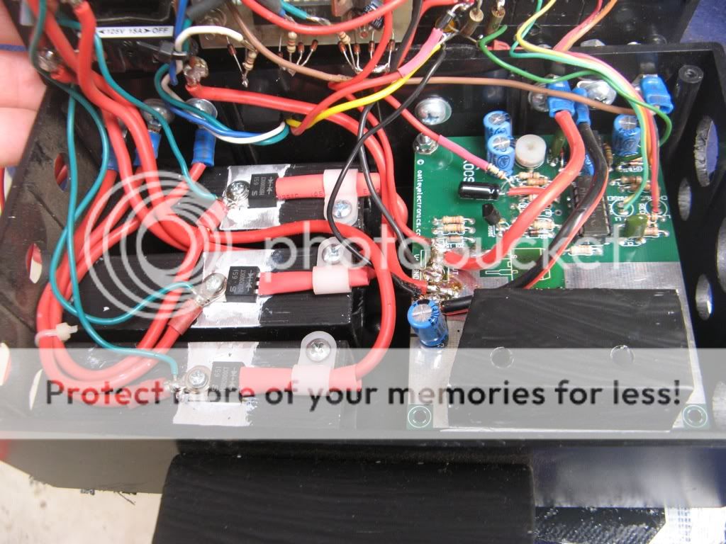
When we arrived home, I replaced the failed MOSFET by a pair of MOSFETs connected in parallel, and mounted on an external heatsink. This comprised a piece of copper plate adapted from some old kitchen utensils from a second hand shop and a small PC CPU heatsink.
I used a small heat shunt to prevent the MOSFETs from overheating as I soldered their tabs using a small gas torch.
Solar Regulator Failure
During our Cape York trip, the solar regulator failed. This was caused by the higher current being generated by the new 200 W array.
The current is controlled by a power MOSFET soldered to the rear of the regulator circuit board, which contains a small heat sink.
 |
| The MOSFET was mounted under the PCB where the brown patch is |
 |
| The MOSFET has overheated causing the solder to melt and it slid down the board |
When we arrived home, I replaced the failed MOSFET by a pair of MOSFETs connected in parallel, and mounted on an external heatsink. This comprised a piece of copper plate adapted from some old kitchen utensils from a second hand shop and a small PC CPU heatsink.
I used a small heat shunt to prevent the MOSFETs from overheating as I soldered their tabs using a small gas torch.
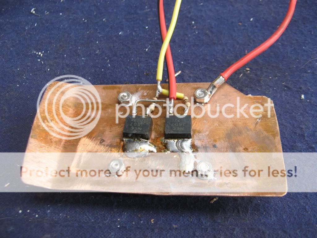 |
| I used a small gas blow torch to solder the MOSFETs since the copper sheet absorbs so much heat |
 |
| A PC CPU heat sink bolted to the rear of the panel |
The new assembly was rewired in alongside the original PCB vertically to allow cooling air to pass over it.
 |
| New heatsink fied alongside the circuit board in the vertical airflow |
This new arrangement works fine and should be capable of controlling up to 400 W of solar panels if more are added in the future.
No comments:
Post a Comment