Welcome to David and Janet Ribbans blog

We live in Adelaide, South Australia and enjoy travel in the Australian outback in our Oka 4WD motorhome, hence the blog title.


To quickly locate any of our more than 80 travel and technical articles, use the drop down menus below or scroll down the lists in the right hand sidebar. But please read the disclaimer first, we've tried to be accurate and current but things can change...
You can also visit the official Oka 4WD website here.

Pandora Web Archive


We're now honoured to have our blogs archived
on the National Library of Australia's Pandora Web Archive.
Bookmark this link to the archived version in case anything ever goes wrong with Google, or I accidentally hit "Delete All" in a fit of pique. The drop down menus above might not work in the archived version but everything else should...

Thursday 30 June 2011

Fixing the Seat Reclining Mechanism

The seat recliner control on my drivers seat is failing and the seat back won't stay up. The teeth on the internal locking ring are worn.

"Moving" part on the left attaches to the seat back, "fixed" part on the right attaches to the seat base.
How it works

The adjuster comprises 2 parts, the "moving" part which is fixed to the back of the seat, and the "fixed" part which is attached to the seat base and on which the adjusting arm is attached (it goes through the centre of the "moving" part).

On the fixed part of the adjuster there are three internal cams with toothed edges which are held by a spring loaded triangular plate against fine teeth on a ring on the moving part, but those teeth have worn flat in places so the seat gives way if I lean backwards. The lever releases the spring allowing the cams to disengage with the ring and the seat back can then move forwards or backwards.

The main spring, which causes the seat back to fold forward when released, is mounted on the opposite side of the seat and is completed independent from the adjuster.

Teeth on the locking ring worn smooth at the most used seat back position
Toothed cams which mesh with the locking ring
I previously turned the cams over so the less worn edge was in use and that worked fine several years but now it's broken again.

Temporary Fix

I've effected a temporary fix to the reclining mechanism.

The mechanism can be disassembled by turning the 4 eccentric locking heads using vice grips until the 2 sections come apart. The adjuster arm will need to be straightened a small amount so that it can slip through the moving part (clamp the mechanism in a vice, slip a piece of pipe over the arm and lever gently).

I reconstituted the ring teeth using a hammer and cold chisel to give the cam teeth something to bite on.

Reconstituted teeth
I fitted shims under the cams to allow them to act on a hitherto unused part of the ring teeth. (Plastic milk cartons are a good source of shim material).

Shims fitted under the toothed cams
I drilled the rings and fitted an "R" pin to lock the seat in position. Actually this was more difficult than anticipated as the outer (moving) ring is peen-hardened and took a lot of drilling. I also drilled a few extra holes on the inner (fixed) ring, which is softer, to accommodate other seat angles. The extra holes only need to be a few mm apart so the same return hole for the "R" pin clip can be used.

I slipped a large washer (not shown) on to the "R" pin to provide something meaty to pull on and when the seat needs to be tilted forwards, it's very quick to pull out the pin, just like a grenade.

An "R" Pin to hold the seat back in position
The "R" pin is a belt and braces solution which will prevent a sudden collapse occurring on an outback trip, but even without it you can usually jam something behind the seat, as we did when the problem first happened (on the west coast of Tassie).

Of course this fix doesn't take the place of a properly functioning mechanism but it works fine for the time being.

The Cause

I suspect the damage was caused in the 1/2 million km that our Oka had done before we bought it, especially if the lever wasn't fully released before reclining the seat, allowing the teeth to grind over each other. It first failed several years ago and we do use the mechanisms quite often to provide access behind the seat but without abusing them.

Dirt build up probably doesn't help and once the teeth don't mesh fully, they start slipping, which will only escalate the wear problem.

Saturday 25 June 2011

Under Wheel-Arch Storage Boxes

Our Oka is a bus model converted to a motorhome so there is limited internal space for storage of heavy spares, except in the rear hatch area. However that area is behind the rear wheels and, with a heavy spare wheel gate mounted across the rear, results in a lopsided (lop-fronted?) front/back weight distribution.

So I'm always on the look out for additional external storage areas on our Oka, especially low down (for heavy objects), to relocate weight from the rear to the front/middle and to free up rear space.


For sometime now I've been eyeing up the cavernous space under the front wheel arches. We previously fitted water tanks under the wheel arches of an old Land Rover for a round the world trip so I know it works, if you leave sufficient space for wheel movement.

443636cb-2011-06-25-09-17.jpg

The huge space under the front wheel arches was just begging to be used

Further on I've describe how I made use of this space with some simple boxes, accessed from under the seats, but first, here are some of the external storage spaces we've already used.

Spaces Already Used

Making use of the wheel arch space came only after we've already used pretty much all the obvious spaces on the Oka:

  • the area behind and alongside the fuels tanks for:

443636cb-2011-06-25-09-17.jpg

10 litre removable waste water tank and 4.5 kg gas bottles

    • the space outside the RHS fuel tank for a thin water tank (made from 90mm PVC pipe to hold 25l of shower water),
  • 443636cb-2011-06-25-09-17.jpg
  • 25 litre "snake tank". People called it a snake tank, so Janet painted a serpent on it.
  • the space behind and below the passenger seat (directly opposite the air filter) for:

443636cb-2011-06-25-09-17.jpg

A 3rd battery. There is still a big unused space above the battery.

  • the spaces under the rear bull bars for:

443636cb-2011-06-25-09-17.jpg

A reserve gas bottle on the LHS

443636cb-2011-06-25-09-17.jpg

A frame for a jack and 2 axles stands on the RHS (empty in this photo)

  • the space behind the front mud flaps for:

443636cb-2011-06-25-09-17.jpg

Water containers and air compressor controls on the LHS

443636cb-2011-06-25-09-17.jpg

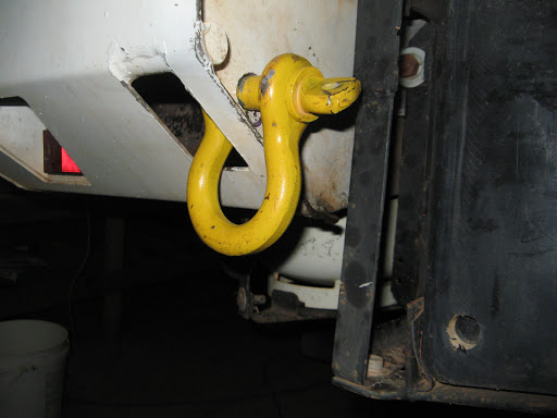
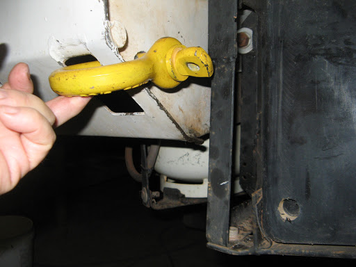
A box for recovery gear on the RHS (winch strap, bow shackles, rope etc)

  • the space below the centre of the floor for 2 water pumps, gas regulator, and gas and water tank change over taps (accessed via a floor hatch).
  • 443636cb-2011-06-25-09-17.jpg

    Internal floor hatch

    • on the front bullbar a Hi Lift jack is stored, together with 2m of 125mm PVC pipe used to hold awning poles, sand flag pole, antenna poles,

    443636cb-2011-06-25-09-17.jpg

    Hi Lift jack and pole storage pipe on front bullbar

    • on the rear wheel ladder we have a coiled airline pipe, water hoses, a pair of levelling wedges and a long handled spade,

    443636cb-2011-06-25-09-17.jpg

    The rear gate is full up with stuff

    • the rear hatch internal space is modified to use as 4 separate tool boxes, with the top as a work bench.

    443636cb-2011-06-25-09-17.jpg

    Rear hatch tool box mods

    443636cb-2011-06-25-09-17.jpg

    Rear hatch in use as a tool box and work bench

    Front Wheel Arch Space

    The space between the top of the front tyre and the bottom of the floor plate is at least 200mm at the absolute maximum possible travel of the suspension (with 285 x 19.5 inch tyres), so I have fitted a 125mm deep box under each wheel arch, which should allow adequate worst case clearance.

    443636cb-2011-06-25-09-17.jpg

    Storage box mounted under the drivers seat. It would be better if they fitted right across the available space.

    The shock absorber has room to move and its bolt is still accessible.

    I did have to identify possible strong points for mounting the boxes and watch for the location of, and access to the shock absorber mounts. These limit the available width of the boxes to about 200mm, without intruding on the wheel spat area, or making the mounting/sealing arrangements unnecessarily complex.

    I happened to have a long aluminium box originally designed to hold 2 jerry cans on a roof rack, so I cut it in half, blocked up the open ends and fitted some mounting angles to the tops. At 500mm long, they are not quite as long as I would have liked, but beggars and choosers etc. It would be better if the boxes stretched the full 700mm right across the wheel arch to reduce the number of cavities that mud, water and dust can penetrate.

    It would be an easy job to fabricate or adapt some simple boxes to fit. I did initially look at adapting some small steel tool boxes or army surplus "ammunition" type boxes before remembering my nice long aluminium box. Plastic boxes should be avoided however, since they will be exposed to high speed rocks, sand and water thrown up by the wheels, not to mention shock and vibration.

    443636cb-2011-06-25-09-17.jpg

    A long aluminium box cut into 2.

    Access to the Boxes

    Access is via a simple hatch door under the seat as they are intended for storage of rarely used items, such as wheel bearings, UJ's etc. You wouldn't want to store often used items here since removing the seat is a bit of a pain, but a side access plate could be fitted, bearing in mind it will be exposed to the elements and wheel driven sand, water, rocks etc., and it would need to be very secure.

    443636cb-2011-06-25-09-17.jpg

    Access hatch under the seat.

    443636cb-2011-06-25-09-17.jpg

    Simple slide-in hatch covers, held in place by M6 captive nuts.

    Mounting the Boxes

    The seat frames provide suitable strong points for mounting the boxes as you don't want them to fall off, scattering your spares along the track. However, the bottom of the front base of the seat sits quite close to the frame so thin headed bolts (countersink or no washers) will be required or the seat fixing won't locate correctly. I used M8 bolts.

    443636cb-2011-06-25-09-17.jpg

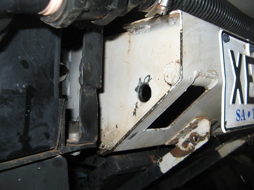
    Hatch cover in place. Note the mounting bolts on the seat frame. The 2 other bolts are close to the door frame. 

    While preparing the wheel arch I discovered (actually re-discovered) some rust holes in the floor plate around the seat frame. These needed to be treated before mounting the boxes.

    I painted the boxes with under-seal for protection, and fitted thick foam sealing strips around the top surface (since the bottom of the floor pan is not flat) to reduce the ingress of the aforementioned mud, water and dust. I am always torn between fully sealing a container to keep out water and dust, or accepting the inevitability of leaks and fitting drain plugs. For these boxes I've attempted both. I've sealed them as best I can but provided blanking plugs on the bottom so that any water/dust that does penetrate can be more easily removed.

    The Contents

    The boxes have a volume of around 10 litres each, which doesn't sound much, but it's surprising how many spares you can fit into such a space.


    443636cb-2011-06-25-09-17.jpg

    The access hatch is around 150 mm square, but could be longer.

    The kinds of things we store in these boxes are:

    • Wheel bearings and cups (1 of each type), lock washers and tab bending puller
    • Bearing locknut socket (2 1/2 inch box spanner)
    • Freewheeling hub spares (the plastic bits inside can break)
    • Gear ball joint
    • Oil seals (rear hub)
    • Spare UJ
    • Brake pads (1 of each type), calliper springs, screws and clips
    • Clutch cable (old but suitable for repairing clutch, throttle and handbrake cables)
    • Gas bottle to airline pipe (emergency "air" supply)
    • Hi Lift jack extension (for winching)
    • Hi Lift jack overhaul kit (actually the old bits after overhaul)
    • Lift Pump and gasket
    • Suspension pins and bushes
    • U-Bolt and nuts

    I wrapped the heavy items in bubble wrap to protect them both from vibration and the possiblilty of water damage.

    The result is that I have relocated more than 10kg of weight from our rear compartment to a lower point, nearer the front, and I've also freed up 20 litres of space in the rear.

    Sunday 5 June 2011

    Rear Towing Points on an Oka

    If you have rear bullbars on your Oka, but no bar (we used the rear space for extra fuel tanks), rear ing points can be easily added if you have built in reinforced high lift jack points. This applies mostly to full body models.

    Drill a 22mm hole (or whatever size fits your D or Bow shackle pin snugly), just behind the high lift jack points on the side plate of the bullbar frame. The hole should be low enough so the shackle can be lifted to at least the horizontal position.

    IMG_5768-2011-06-5-23-59.JPG

    22mm holes in the bullbar side plate

    The D or Bow shackle will fit neatly through the jacking point and provide strong ing points on either side of the Oka.

    IMG_5765-2011-06-5-23-59.JPG

    IMG_5766-2011-06-5-23-59.JPG

    Bow shackle located on the bullbar

    The bullbar side plate is 8mm steel and is bolted directly to the Oka chassis using the same 16mm bolts provided for holding a bar. It's the equivalent of the points built into the front bullbar and probably stronger. It's also the primary member used by the high lift jack in raising the vehicle.

    Using D or Bow shackles on both sides and an equalisation strap (or a tree trunk protector), the stresses can be shared and equalised between each bullbar when the Oka is being towed backwards, or while pulling another vehicle or object off a track.

    Notes:

    1) Shackles with at least a 4.75 Tonne rating are recommended (equivalent to 10,500 lbs). If you need more than this you probably need a crane not a truck.

    2) A webbing strap will fit a Bow shackle better than a D shackle.

    3) A steel plate or large washers with 22 mm holes could be welded to the side plate to stabilise the action of the shackle if required, or packing pieces can be added to the shackle pin as shown below.

    shackleloads-2011-06-5-23-59.jpg

    4) Don't leave the shackles attached whilst driving, the pins will vibrate loose and the shackle will drop off.

    5) Bolt-on hooks area available in 4WD shops but they are not as reliable as as D or Bow shackles since you are dependent on the strength of a hook (not a closed steel loop) and the integrity of 2 or 4 small bolts. In any case I couldn't find anywhere suitable to mount them.

    If you have to use bolt on tow points, use something like these (from TJM), ie a closed steel loop with at least 3 high tensile fixing bolts (and somewhere substantial to mount them).

    PastedGraphic-2011-06-5-23-59.png

    Not this type:

    PastedGraphic1-2011-06-5-23-59.png