Welcome to David and Janet Ribbans blog

We live in Adelaide, South Australia and enjoy travel in the Australian outback in our Oka 4WD motorhome, hence the blog title.


To quickly locate any of our more than 80 travel and technical articles, use the drop down menus below or scroll down the lists in the right hand sidebar. But please read the disclaimer first, we've tried to be accurate and current but things can change...
You can also visit the official Oka 4WD website here.

Pandora Web Archive


We're now honoured to have our blogs archived
on the National Library of Australia's Pandora Web Archive.
Bookmark this link to the archived version in case anything ever goes wrong with Google, or I accidentally hit "Delete All" in a fit of pique. The drop down menus above might not work in the archived version but everything else should...

Tuesday 29 December 2009

Adelaide to Brisbane 2009

Our Trip to Brisbane

In 2009 we had a lot of dramas, but none of them stopped us going up to Brisbane (actually Ipswich) in November for Janet’s cousin’s twin daughters 40th birthday bash (I wish they were more closely related, it would save keystrokes). We left on 7 November and were away for about 4 weeks, getting back just in time to not miss all the Christmas silly season stuff.

We went via the Barrier Highway through Broken Hill, Wilcannia, Nyngan, Cobar, Coonabarabran, Narrabri, Bingara, Glen Innes, Tenterfield and Warwick to Ipswich.

We had a really good time in Brissie, staying with Janet’s cousin. The bash was a fancy dress party and I went as a Maharajah and Janet as a Maharini. If you don’t want to see someone in a turban pole-dancing around a Hills Hoist, look away now.

40th252BB252Bday252B2009252B091.JPG-2009-12-29-07-26-2009-12-29-17-56.jpg

Janet and David in their Maharajah costumes.

Nov252B2009252BParty252B086.JPG-2009-12-29-07-26-2009-12-29-17-56.jpg

David a bit later on needing the support of a clothes hoist, and yes that is a snake up his sleeve.

40th252BB252Bday252B2009252B185.JPG-2009-12-29-07-26-2009-12-29-17-56.jpg

Who called the police? Oh, it’s OK, he was the host in disguise.

Before we left, our hosts shot off to Tassie for a few days leaving us in charge of their house, liquor supplies, BMW etc. Living in their house, driving their car and raiding their fridge felt like identity fraud.

When we eventually dragged ourselves away, we had been gone 4 weeks and did 4500 km, which is a very long way for a birthday party. We would have been away longer but it was very hot and humid and you just can’t do sight-seeing when it’s over 40ยบ.

IMG_1333-2009-12-29-07-26-2009-12-29-17-56.jpg

Part of the worlds largest Solar System Display, near the Warrumbungles National Park, around 100 km across, centred on the Siding Springs Observatory.

As it was, we did do some 4WDriving in a rain forest in the Border Ranges National Park, where Janet collected a leech on her foot, a tick on her leg and saw a snake close up, too close in her opinion. We also visited our friends Tim and Brenda in Byron Bay on the way back, and returned across the Barrier Highway through some stunning desert scenery between Broken Hill and Cobar.

IMG_1273.JPG-2009-12-29-07-26-2009-12-29-17-56.jpg

A roadside stop in southern Queensland, (which is not between Broken Hill and Cobar).

On the way to and from Brisbane (which is more than a week’s drive each way), we stayed at a delightful free campsite alongside the Gwydir River in the town of Bingara, in northern NSW. The town’s forward thinking council are actively attracting motor homers to come and stay in the town for free, in the expectation (accurate as it happens) that they will patronise local businesses and keep the town alive and thriving. We fully support that kind of RV Friendly symbiotic environment.

IMG_1159.JPG-2009-12-29-07-26-2009-12-29-17-56.jpg

The Gwydir River campsite in Bingara.

HF Antenna

On our trip we managed to check out our new antenna for the HF radio in our Oka. It’s a 9 m high fibreglass telescopic whip antenna to enhance our communications abilities when we are remote from civilisation, which we seem to be most of the time.

9 m might seem a tad large compared with your average car radio aerial, but when it comes to HF radio transmissions, size definitely does matter. We do, however, have to maintain a keen watch out for thunderstorms as it could be attractive to lightning. In a thunderstorm, you don’t want to be the tallest thing around.

For the technically minded, 9 m happens to be a 1/4 wavelength on our primary communications frequency of 8.022 MHz which is the optimum length for effective transmission. It can give us a communications range of up to 3,000 km, far enough to seek assistance from any part of Australia.

IMG_1338-2009-12-29-07-26-2009-12-29-17-56.jpg

Our 9 m HF antenna raised in a bush camp at dawn somewhere in outback NSW.

(Actually I know exactly where it was, and so I should with all the technology at our fingertips. It’s location is S31’ 33.72”, E146’ 55.19”, which is 25 km west of Nyngan, in bushland about 1 km south of the Barrier Highway, across the railway line and left at the next bush).

ScreenShot2018-01-11at8.20.10am-2009-12-29-17-56.png

One of the other nice places we stopped at on the way back was Peterborough in the mid-north of South Australia. They have an excellent railway museum there with a round house, engines etc, but unfortunately no working locos at the moment.

It’s ironic that the main Trans-Australia railway passes through the town but you can’t actually go there by train. I’ve asked them to fix that.

IMG_1405.JPG-2009-12-29-07-26-2009-12-29-17-56.jpg

What any small boy would want to do.

Wednesday 16 December 2009

SuperRod 9 Metre Whip Antenna for HF

We use the VKS737 HF radio network to keep in contact with the world while we are camped in remote locations.

We normally used a fairly short (2m) tapped whip antenna, which is quite convenient and works reasonably in most places, but we recently installed an alternative 9m fibreglass whip antenna. It take a little longer to erect but at a 1/4 wavelength, it's the optimum length for using Channel 2 on 8022 KHz and provides the best possible communications on this frequency.

Using this antenna we invariable receive a 5 by 5 report (the highest) from VKS bases when requesting a radio check. I've also determined that it can be used as quite an acceptable shortwave antenna for receiving ABC and BBC broadcasts (amongst many others) over a broad range of frequencies from 6 to 10 MHz, although with some loss of efficiency either side of 8 MHz.

IMG_1338-2009-12-16-09-27.jpg
The 9m SuperRod in operation on our Oka, somewhere in outback NSW

The antenna is based on a 9m, 9 section, telescopic fibreglass fishing pole, but with a wire inserted up the middle. They are called SuperRod Antennas and I got mine from The Electric Bug in Adelaide without any mounting hardware, but a cheaper alternative could be to make one using a fishing pole from angling shops. (See here where you can buy 9m bare poles for around $40 plus freight, and fit the wire yourself, see here for some assembly ideas. For use on 8022 KHz, none of the loading coils are necessary). If you are really keen you can import a much tougher pole from Spiderbeam in Germany. They are not that expensive at Euro 66 (AUD 100) plus freight for a 12m pole.

The wire doesn't have to run up inside the antenna, it will work just as well if the wire is wrapped around the pole, or if it is just attached to the tip and the pole used as means of getting it vertically into the air. It just looks neater inside. The pole doesn't even have to be 9m long either, only the wire has to be that long.

Whilst the antenna works well, there are a few of challenges to its installation and operation:
  • Mounting: It needs a sturdy mounting point on the bull bar or similar because, although it's not heavy, as it moves around in the breeze it places a considerable strain on its mount. It should not be used on a moving vehicle while raised. In this mode the antenna is acting as one half of a vertical dipole with the vehicle and ground beneath it providing the other half.
  • Antenna Wire: When collapsed, the 9m of wire needs to be coiled or wound up to keep it straight and tidy. A kinked wire won't run up or down the antenna smoothly.
  • Erecting: (Important: first read the Power Line warning at point 7 below. Note this sobering story from the ABC). The sections must be extended tightly and "screwed" into each other as the antenna is being erected, or they can slide down inside each other, either during operation as the wind blows or as you are lowering the antenna, trapping the wire and loosing their telescopic sequence.
  • Lowering: The wire must be pulled gently and continuously out of the bottom of the antenna as each section is separated, or it will get trapped and kinked in the bottom section which is frustrating to unravel and the wire can break.
  • Connecting: The antenna needs connections made to the radio lead. It doesn't just plug on.
  • Frequencies: It primarily intended for Channel 2 (8022 KHz) and needs some mods to work on Channel 1 (5455 KHz) or RFDS frequencies.
  • Power Lines and Lightning: It's so tall it's a power-line and/or lightning risk.
I have experienced all of the above problems and modified the antenna and mounting arrangements to minimise them.

1) Mounting the Antenna

To mount the antenna, I fitted a length of 50mm PVC pipe (which holds the lower section of the antenna), to an aluminium frame which then slides into a holder, made from aluminium rope track, mounted on the bullbar using 50mm U-bolts. I could have mounted it higher where it might work better but I couldn't then raise it, since the top would be beyond my reach. The PVC pipe has a cap on the bottom to hold the antenna but with a hole in it for the wire to slide through. The whole assembly can be removed, with the wire wound up on an attached reel, for storage inside the Oka.

IMG_1457.JPG-2009-12-16-09-27.jpg
The mounting using aluminium rope track on the bullbar.

IMG_1456-2009-12-16-09-27.jpg
The SuperRod stored safely in the Oka.

2) Keeping the Wire Tidy

After lowering the antenna and extracting the wire, you are left with a 9m tangle of wire on the ground (actually only 8m since 1m is always inside the antenna).

To tidy this up I fitted a cheap hand fishing reel to an aluminium plate with a simple handle to wind up the wire as it is being pulled out, which is a lot easier with 2 people. A notch/slot in the reel holds the connector in place as the wire is wound up.

IMG_1090.JPG-2009-12-16-09-27.jpg
The SuperRod mounted on the bullbar, with a hand fishing reel for winding up the wire.

IMG_1458-2009-12-16-09-27.jpg

The SuperRod lowered and the wire neatly wound up on the hand reel.

You could also wind it around any other kind of former, such as those designed to tidy up extension cables, but it is essential that the wire is not bent too sharply or kinked in the process, or erection and lowering of the antenna will be made more difficult.

3) Telescoping Sections

The smaller sections can drop down inside the larger ones and get jammed, also trapping the wire inside.

This will require a complete disassembly of the antenna to disentangle. A simple solution is to fit a nylon string to the tip of the smallest section and to tie a ping-pong ball or similar sized plastic object (I use the top off a deodorant can) about 50cm from the tip. Then, none of the smaller sections can disappear very far inside the larger ones, and you can pull them out using the nylon string.

IMG_1088-2009-12-16-09-27.jpg
A bead to hold the nylon string in place.

4) Preventing the Wire from Breaking or Pulling Out

The wire jammed and broke (actually it pulled out of the top section) while I was experimenting with erecting the antenna. 9m of antenna is a bit of a handful to hold and I must have pulled too hard on the wire, and you certainly don't want this to happen in a remote location.

So I disassembled all 9 sections to get at the top section. The red insulated wire as supplied is joined to a fairly thin solid copper wire part way up the thinnest section, since the red wire is too thick to go through the centre hole in the fibreglass. The solid wire is pushed through the tip of the section and presumably glued or crimped in place, but not very securely. This is what failed so I discarded the thin copper wire.

To improve this aspect I drilled a 1mm hole down the tip of the section, just deeper than the crimping band, and securely soldered a 50cm piece of thicker copper wire to the red insulated wire. Then I inserted it through the top section until it protruded from the tip. I soldered a round terminal to the wire sticking out of the end, to prevent it ever slipping inside the rod again. Bending a 6mm loop in the wire would work as well and either method will also provide a means of attaching a nylon string to the top section. A small bead was used to secure the string to the terminal so it all still nests together neatly. A bigger object was then attached to the string as mentioned above, to prevent any of the sections from sliding too far in.

IMG_1087.JPG-2009-12-16-09-27.jpg

A terminal soldered to a thicker copper centre wire after drilling a 1mm hole in the tip.

In retrospect, I found disassembly of the antenna and replacing the wire to be a very useful exercise because I now know how to replace the wire if it ever breaks again while travelling.

5) Connection the Antenna to the Radio

A PL259 socket (or whatever connector you need to match the one on your antenna lead) needs to be mounted near the bottom of the antenna for connecting the coax cable from the radio. You might need to extend the radio antenna lead if it no longer reaches the new bullbar mount. The centre connection of the socket can be fitted with a short wire with a male bullet connector crimped on, to connect to female bullet connector on the antenna wire. The ground (outer) section of the connector needs to be connected to the chassis of the vehicle using a ground cable which is as short as possible. The bull bar frame might be OK as long as that itself is well grounded to the vehicle chassis. Fit a ground cable from the socket to the vehicle chassis just in case.

You can tell how effective the grounding is buy turning on the radio, with the antenna erected and connected, and listening to the level of background noise received. It will change in volume as the grounding is improved or made worse. Maximum noise volume (ie best match with the radio) indicates the improved grounding. This doesn't take the place of proper antenna tuning and matching tests but unlike tapped whip antenna bases, the SuperRod has no matching components, only a centre wire, so some experimenting is necessary.

With a tapped whip antenna mounted as well as the SuperRod, I was able to switch the radio lead from one to the other and confirmed that the SuperRod certainly had better reception (higher signal strength) on 8022 KHz than the tapped whip. As to be expected, it also received background noise better as well.

[Note: This improvement in performance over the tapped whip antenna was confirmed during a recent 3 month trek up to the tip of Cape York. Invariably, when using the SuperRod, the base operator commented on the excellent signal strength. However, I didn't use the SuperRod antenna every day because it takes time to erect or it was too windy. It was used when signal conditions were otherwise poor, or when more time was available before a sked finished to erect it.]

In high noise environments, such as at home in a more dense housing area I’ve found the antenna works well with much less electrical noise pick up when still connected but mounted horizontally from the bullbar and supported on something non-conductive, eg a dry tree branch but I usually rest it on a wheelie bin. It will sag a bit and is more directional this way but it certainly increases the signal to noise ratio. In this mode the antenna is now acting as one half of a horizontal dipole but with the vehicle simulating the other half.

6) Using the SuperRod on Channel 1 (5455 KHz) or other VKS frequencies

The 9m SuperRod can also be used directly on VKS737 Channel 1 on 5455 KHz, with some loss of performance since it's not matched to the transmission frequency. It really should be 13.75m long to be a 1/4 wavelength at that frequency.

Channel 1 performance can be improved by fitting a loading coil so it looks to the radio as if it were a 13.75m antenna, but they cost around $40-50 commercially, but one could be wound much more economically. I found that a simpler solution was to attach about 4.5m of additional wire between the radio antenna lead centre wire and the SuperRod wire connection and to droop this loosely over a nearby bush/tree branch. It will work better there than just lying on the ground, but keep people away from the wire when transmitting to avoid radiation burns. This is not as good as a tuned loading coil but is adequate as a fallback.

The wire I use is the type sold in hardware stores for use with low voltage garden lighting systems. I has a 10 amp current carrying capacity and nice thick insulation since it's intended for outdoor applications, so it's ideal for laying on the ground or throwing up trees. It's usually twin conductor but is easily split into single conductors.

A better but more tricky alternative is to connect the extra wire to the top of the antenna, using the solder terminal fitted at the tip, and to extend that wire out sideways and/or upwards as far as possible, using a piece of nylon string attached to the end and fixed to a tree/bush etc. It will now be the correct length and nice and high, although the antenna will bend a fair bit and its radiation pattern won't be optimum.

Note that similar bent antennae, called Near Vertical Incidence Skywave (NVIS) systems, are available from Codan, Barrett etc, as in the sketch on page 2 of the Codan brochure here. This system optimises the skywave signal path for short range communications (inside the normal skip distance) by directing some of the transmitted energy upwards at an angle, rather than horizontally, which reflects off the ionosphere to closer destinations.

The Royal Flying Doctor Service (RFDS) uses frequencies in the 5 MHz range (5145, 5110, 5300, 5360, 5410 KHz depending on location of their bases) which are similar enough to the VKS737 Channel 1 frequency of 5455 KHz that the SuperRod with the additional 4.5m of wire should be capable of using them effectively. Some tuning of the exact length could be done as required using the formula (300/Frq MHz)/4. For Frq=5.3 MHz (5300 KHz), for example, an additional wire length of 4.8m would required.

See the RFDS frequency and VKS737 SelCall usage on this VKS737 document.

Note that Selcall access to the RFDS via an HF Radio (with VKS737 Selcall capabilities) is now the preferred and most reliable method of contacting the RFDS. Their radio frequencies may not be continuously monitored.

The SuperRod could readily be used on frequencies higher than 8mHz (ie a shorter antenna for 10, 12, or 15 mHz) by cutting the wire inside to the appropriate length and only raising the antenna sufficiently to elevate that length of wire. Of course, to use it for several frequencies would mean having small connectors part way along the wire sufficiently small to fit inside the telescopic section (or abandon the inside wire in favour of a spiral wound external wire).

Approximate wire lengths would be:
Channel 3       11612 kHz                 6.45m
Channel 4       14977 kHz                 5m
Channel 7       10180 kHz          7.36m

7) Power-Line and Lightning Warning

Be very aware of overhead power lines, see this recent sobering story.

Before raising a SuperRod, first look upwards to ensure there are no power-lines within range (which maybe only 6 m above ground level and well within the reach of a 9 m antenna), especially in populated areas such as caravan parks, national park camping areas, roadside rest areas or boat ramps. It's too easy to just raise the antenna, section by section from bullbar level, without first checking upwards. You could get a very nasty (and fatal) surprise, and in any case, your radio won't work very well in the proximity (~100m) of power lines due to the noise induced from the power transmission. Transmitting probably won't be affected but reception certainly will.

A tall antenna such as the 9m SuperRod will also be very attractive to lightning, so be very careful about using it when there are thunderstorms about. In particular, don't rely on lightning protection devices and don't leave it up at night if there is the slightest chance of strong winds or thunderstorms springing up unannounced.

Remember, in a thunderstorm you don't want to be the tallest thing around.

References:

The WANSARC radio club has a useful review of the SuperRod on page 5 of this issue.

Monday 14 December 2009

2009, An Unexpected Year

To all our friends around the world.

Well, the year itself wasn't unexpected but much of what happened was.

The first part of the year actually went pretty much according to plan, maybe too smoothly. There was the usual Australia Day BBQ followed by a hot summer, then a phase of repairing and upgrading the Oka in preparation for another outback trek, this time across Western Australia. Read on because it didn't happen that way.

Janet's 60th Birthday

By popular demand, Janet's birthday had been deferred for several months, since we'd only just returned from a 14,000 km trek, and we eventually held a commemoration in conjunction with an Australia Day BBQ on, well, Australia Day.
A collage of Janet's life in pictures

Interestingly, in a snap poll of the 20 or so people present, only one had actually been born in Australia. Quite what that meant in the context of our Australia Day celebrations we didn't pursue, due to too many non-functioning brain cells. But it was also Chinese New Year's day so, in true Aussie style, anything is worth celebrating if it has, as its basis, the legal consumption of alcohol.

The Victorian Bushfires

Severe bush fires in Victoria took up most peoples attention in February with 173 people killed and thousands of homes and lives destroyed.

How could anyone combat this? (ABC Photo)

The answer is no one could. It was an unstoppable ball of fire, a pyroclastic cloud consuming everything in its path and killing by radiant heat alone until nature took a hand, and the picture below shows the sad result for so many people.

(ABC Photo)

The heat was tremendous with many towns recording 48ยบ temperatures. In Adelaide it officially reached 46ยบ, or 115ยบF on the old scale, and railway lines buckled in the heat.

(ABC Photo)

On the streets and at the beach it exceeded 50ยบ.

(ABC Photos)

There were a few lighter moments though, this sculpture of a melted ice cream truck says it all about our long hot summer.

(ABC Photo)

The Lower Lakes

We went and had a look at the lower lakes region after many years of severe drought and water shortages. It's more than 7 years since the River Murray actually reached the sea and Lake Alexandrina has become a sandy basin fit only for land yachting.

The Jetty at Lake Alexandrina

After the summer we were planning to "do" the Connie Sue and Gunbarrel Highways in outback WA (around 2,000 km of rough outback tracks for those who are not familiar with them), and out to the west coast for some sea breezes. But it didn't quite happen that way.

We had a quintille of problems which kept us at home until late in the year.

Scary Health Moment

First I had a health scare when the doctor found a small lump on my prostate following my normal annual check-up. That required a biopsy, which confirmed a small amount of cancer, followed by a full day of x-rays, MRI's and bone scans to determine its extent. Fortunately it is under control for the time being, not life threatening and hasn't spread, and even if it does grow, there are surgical solutions to control it. The worst they found was a gall stone which shone out like a super-nova on the x-rays, but nothing to worry about. But all this took a couple of anxious months to resolve.

Toothache in the Differential

Then I found a broken tooth on the front differential gear of our Oka, (the opposite of a gall stone), which meant a complete strip down and rebuilding of the front axle. That's now finished and we are back on the road but it kept us busy for a few more weeks. All good experience and I've written it up on our blog here.

The damaged gear.

Bella's Operations

Then, just as we finished with that, our dog Bella had to have a large cancerous lump removed from her leg and it all took around 3 months for the wound and skin grafts (not to mention my credit card) to heal, before we could lumber Mark and Mollie with looking after her while we were away.

Poor Bella, looking just a bit sorry for herself after her skin graft operation.

So we were stuck at home through the cold and wet winter (by Adelaide standards), all packed up and ready to go but couldn't leave. Very frustrating, but at least the vegie garden was blooming. We had a world record crop of broad beans (pity no one likes them except me), caulies, broccoli and beetroot and we managed to raise seeds from squash, pumpkins, sweetcorn, silver beet and tomatoes which are now all flourishing in the summer heat. Strawberries we grow too, but only for the birds and millipedes to eat.

Then while all that was happening there were more dramas:

A Sad Funeral

One of my long term friends and colleagues, Nigel, a jogger and non-smoker, succumbed to lung cancer and his funeral was both an enlightening but a very sober affair. Around 300 people turned out which was an indicator of his popularity.

The Car's Gearbox

Then the car's automatic gearbox, which kept jumping out of gear and generally messing around at inconvenient moments, needed an overhaul. Luckily it only cost us a small fortune when I was expecting it to be a large one.

Thigh Pains

Janet had been experiencing some thigh/hip pains but an ultrasound determined that they were caused by someone or other's syndrome and she needed some injections to regrease the joints, which have only been partially successful.

The Water Tank Leak

Then in October, the solar hot water tank on the roof burst sending lots of hot water into the roof. Most of it went down the tiles and into the gutter but sufficient got though the tiles to cause the hall ceiling to sag in several places.

Strangely, the smoke alarm in the hall went off at 2.30am (just when your brain is not awake at all) and it was raining. Janet felt some splashes on her leg so we assumed a bit of rain had got in but I don't understand how that set off the alarm. So we put a bucket under the drip, took the batteries out of the smoke alarm, stopped worrying about the technicalities involved and went back to bed.

In the morning it was still dripping, the bucket was full, but the sun was shining and there was no sign of rain. It was then, being slow learners, that we realised that the tank on the roof was leaking and it got progressively worse as the day wore on.

We had the tank replaced the next day (it was 20 years old so a "bit of a leak" was not unexpected), but getting the hall ceiling done was more problematic. The hot water caused the Gyproc panels to sag and potentially collapse so I had to prop them up pending finding someone to fix them.

The sagging ceiling panels in the hall.

Fortunately Mark's friend Heath is in the wall board/plastering business and he gave us a quote and the insurance covered the cost of the ceiling repair but not the tank.

HF Antenna

I did manage to install another antenna for our HF radio in our Oka. It's a 9 m high fibreglass telescopic whip antenna to enhance our communications abilities when we are remote from civilisation, which we seem to be most of the time.

9 m might seem a tad large compared with your average car radio aerial, but when it comes to HF radio transmissions, size definitely does matter. We do, however, have to maintain a keen watch out for thunderstorms as it could be attractive to lightning. In a thunderstorm, you don't want to be the tallest thing around.

For the technically minded, 9 m happens to be a 1/4 wavelength on our primary communications frequency of 8.022 MHz which is the optimum length for effective transmission. It can give us a communications range of up to 3,000 km, far enough to seek assistance from any part of Australia.

Our 9 m HF antenna raised in a bush camp at dawn somewhere in outback NSW.

(Actually I know exactly where it was, and so I should with all the technology at our fingertips. It's location is S31' 33.72", E146' 55.19", which is 25 km west of Nyngan, in bushland about 1 km south of the Barrier Highway, across the railway line and left at the next bush).

Our Trip to Brisbane

But despite all these dramas, none of them stopped us going up to Brisbane in November for Janet's cousin's twin daughters 40th birthday bash (I wish they were more closely related, it would save keystrokes). We left on 7 November and were away for about 4 weeks, getting back just in time to not miss all the Christmas silly season stuff.

We had a really good time in Brissie, staying with Janet's cousin. The bash was a fancy dress party and I went as a Maharajah and Janet as a Maharini. If you don't want to see someone in a turban pole-dancing around a Hills Hoist, look away now.

Janet and David in their Maharajah costumes.

David a bit later on needing the support of a clothes hoist, and yes that is a snake up his sleeve.

Who called the police? Oh, it's OK, he was the host in disguise.

Before we left, our hosts shot off to Tassie for a few days leaving us in charge of their house, liquor supplies, BMW etc. Living in their house, driving their car and raiding their fridge felt like identity fraud.

When we eventually dragged ourselves away, we had been gone 4 weeks and did 4500 km, which is a very long way for a birthday party. We would have been away longer but it was very hot and humid and you just can't do sight-seeing when it's over 40ยบ.

Part of the worlds largest Solar System Display, near the Warrumbungles National Park, around 100 km across, centred on the Siding Springs Observatory.

As it was, we did do some 4WDriving in a rain forest in the Border Ranges National Park, where Janet collected a leech on her foot, a tick on her leg and saw a snake close up, too close in her opinion. We also visited our friends Tim and Brenda in Byron Bay on the way back, and returned across the Barrier Highway through some stunning desert scenery between Broken Hill and Cobar.

A roadside stop in southern Queensland, (which is not between Broken Hill and Cobar).

On the way to and from Brisbane (which is more than a week's drive each way), we stayed at a delightful free campsite alongside the Gwydir River in the town of Bingara, in northern NSW. The town's forward thinking council are actively attracting motorhomers to come and stay in the town for free, in the expectation (accurate as it happens) that they will patronise local businesses and keep the town alive and thriving. We fully support that kind of RV Friendly symbiotic environment.

The Gwydir River campsite in Bingara.

One of the other nice places we stopped at was Peterborough in the mid-north of South Australia. They have an excellent railway museum there with a round house, engines etc, but unfortunately no working locos at the moment. It's ironic that the main Trans-Australia railway passes through the town but you can't actually go there by train. I've asked them to fix that.

What any small boy would want to do.

In Summary

Surprisingly, apart from all our dramas, all is well here. Global warming has deserted us for the time being after a record hot November and it's quite cool and gently raining. Not enough to water the garden but enough to rust the tools I left out last night.

We've had an interesting if somewhat unexpected year and hopefully we can cope as well with whatever fate hands us next year.

We remain forever grateful that our problems, however frustrating they may be, are trivial compared with the really serious issues that some our friends are having to deal with.

We hope you have a really good Christmas break and good fortune in 2010.

David and Janet

Friday 11 September 2009

GARP Part 2, the Great Axle Reconstruction Project

Intro

In Part 1, I described the events leading to disassembly and repair of the front axle.

Part 2 describes the reassembly process.

Hubs and Spindles

Following on from Part 1 which was initiated by a front end vibration, I have now cleaned up the spindles, removed the diff inner oil seals and checked the bearings for fit on the reground spindles. The shells are a tight fit, or rather, they need accuracy in location or they will jam sideways. Once correctly located the bearings slide and rotate very smoothly. Of course, once the bearings are tightened up the shells shouldn't move or rotate on the spindles anyway.

I removed the rear hub oil seals, using an inside gear puller pressing on a steel bar placed across the hub, but before replacing them, I tried the hubs and bearings on the reground spindles, temporarily reattached to the steering knuckles. This is to ensure they can be correctly assembled without jamming when the hub is offered up to the spindles. Had the inner bearing jammed on the spindle, it would have damaged the new oil seal when the hub was removed.

If the bearings are jamming, smoothing the spindle with some fine emery cloth and careful cleaning with WD40 will help, as will a smear of oil on the bearing surfaces. Older bearings will fit slightly easier than brand new ones.

If the hub and bearings can be successfully located on the spindle without jamming, a new oil seal can be pressed into the rear of the hub, by gently tapping around the edge with a heavy hammer until it's flush with the hub casing. Don't knock dirt from the back of the hub into the bearings.


IMG_1068.JPG-2009-09-11-08-36.jpg

Oil seal inserted into the rear of the hub

Diff Carrier Rebuilding

Refer to Section 4 of the Dana 70 Maintenance Manual (available here) and the Carrier section of the Dana 60 Maintenance Manual (available here) for advice on how to do this. The front axle of an Oka is actually a Dana 60 while the rear is a Dana 70, but there are many similarities and the techniques in these manuals are relevant to both types. In fact there's a host of useful documents available from the Dana website here.

After removing the diff centre carrier, I unbolted and removed the ring gear, knocked the roll pin through and removed the cross shaft and differential gears.

Because it's a heavy item and would be seriously damaged if it fell on the concrete floor, I inserted a sturdy cable through the carrier and tied it to a roof beam so that if it slipped out of the vice whilst being worked on, it would swing clear and only hit me, not the hard concrete.

Removing the ring bolts was easier than anticipated since they should have been torqued to 130 ft-lbs (176 Nm) and Loctited too. I left four of the bolts partly in place and tapped them with a hammer to free up the ring gear, which wasn't very tight anyway. I moved the carrier from the vice to the workbench and then removed the last 4 bolts whilst holding the ring away from any hard objects. I didn't want to have to replace that as well, since ring gears only come as matched pairs with the pinion, which would have made it a much more difficult (and expensive) job.

IMG_1055.JPG-2009-09-11-08-36.jpg

The Ring Gear being removed

The bearing cups came away when removing the diff centre, so I put old socks over each of the bearings to protect them while this work was being done.

I tapped out the roll pin using a length of 5mm steel rod, and the cross shaft then slid out of the carrier.

Removing the differential gears looked difficult since they remained meshed together, but by turning a side gear, the spider gears simply walked themselves around to the opening in the diff and fell out. All 4 gears are seated on thrust washers which might be stuck to the carrier by oily suction.

I smoothed the rusted and pitted surfaces of the ring gear with fine emery paper and WD40 and cleaned them off with Brake Cleaner fluid.

The broken gear wheel will end up in my Museum of Broken Car Parts which is becoming quite extensive.

IMG_1057.JPG-2009-09-11-08-36.jpg 

The diff in pieces ready for reassembly

IMG_1058.JPG-2009-09-11-08-36.jpg

The Differential Gear Set

IMG_1059.JPG-2009-09-11-08-36.jpg

A close up of the offending tooth

Diff Oil Seals

Removal of the Inner Seals

To remove the inner diff oil seals I built a pusher rod made of a metre of 12mm tapped rod with a large steel washer, just the diameter of the rear guide section of the seal, bolted to the other end. A few whacks with a heavy hammer and the seals popped out into the diff chamber. Other people have used a large socket and several extension bars to achieve the same result, but I didn't have the right size socket (or sufficient extension bars). The bar needs to be at least 1 metre long to remove the LHS seal.

This bar, with a sock tied over the washer, also makes a useful tool for cleaning out the oily/muddy sludge from the axle tubes.

IMG_1046-2009-09-11-08-36.jpg

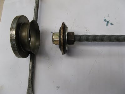
The pusher for removing the inner seals and cleaning out the axle tubes

Installing the Inner Seals

To insert the seals I used a modified 40 mm high pressure water fitting, which just fits inside the seal body, to avoid damaging the plastic parts of the seal with a hammer. The fitting will need to be cut down to about 50 mm long to allow a hammer to be swung inside the diff housing. I drilled and fitted a long bolt to the side of the plastic fitting as a handle, to keep my thumbs well clear of the hammer. A suitable socket might also work. Alternatively a pusher tool could be made up as described in the Dana 60 manual. Any rust or corrosion around the seal location should first be removed and the surfaces smoothed down.

The old seals had silicon gasket sealant smeared around their outer surfaces before insertion, presumably to keep water away from the metal surfaces and prevent premature rusting. Seems like a good idea, as does greasing the seals and guide inner surfaces to help the splined drive shafts find their location.

However, sealant on the seal casing also makes them slippery and more difficult to keep centred as they are inserted. It takes a quite a lot of effort in a confined space to insert the seals straight, since they are a tight fit, and I had to remove and reinsert one of them a couple of times to avoid fitting it crookedly. A pusher tool would certainly be more effective.

Mind the pinion gear, bearing seats and thumbs as you are wielding the hammer, damage to those would be expensive and/or painful.

Clean out all the resulting muck from the diff housing.

IMG_1052.JPG-2009-09-11-08-36.jpg

A modified 40 mm high pressure water fitting would fit inside the body of the seal

Reassembling the Diff Carrier

Before reassembling the diff centre, ensure that the ring bolts and tapped holes in the ring gear are thoroughly cleaned and free of old Loctite.

Before the ring is refitted, the new gear set must be installed, with their thrust washers, and the cross shaft and roll pin inserted. Oil all the parts well before assembly and check for smooth rotation.

Installing the Differential Gears

You'll need about 15 fingers to hold the 4 gears and their thrust washers in the right place but it's not too difficult. Insert the side gears first on their washers, with the carrier horizontal so they can't fall out. Then insert both spider gears exactly 180ยบ apart from either side of the carrier and walk them into the carrier case by turning both side gears in the same direction. If they are not exactly 180ยบ apart on the side gears the cross shaft holes won't line up. I found it easier to slide the saucer shaped thrust washers in behind the spider gears after the gears were in place.

IMG_1063.JPG-2009-09-11-08-36.jpg

Gears reinstalled in the carrier

Once all the gears are in place, centre the the spider gear washers with a finger and insert the cross shaft with the roll pin holes roughly in line. Use a thin bar to turn the cross shaft until the roll pin holes line up and drive in the roll pin. The differential gears are now complete, assuming they all turn smoothly.


IMG_1064.JPG-2009-09-11-08-36.jpg

Driving the Roll Pin home to complete the assembly

Installing the Ring Gear

The ring gear should be replaced in its original orientation (not sure why, it doesn't seem to be a balanced item, but that's what the manual says) and this can be determined from the imprint markings on the carrier made by the ring. There is a cut out on one side of the ring, presumably for oil flow, which will show up as a shadow on the carrier. I also took photos of the stamped markings to confirm it's location.

The manual also suggests replacing the 12 ring gear bolts, but they are very high tensile bolts (SAE Grade 8, equivalent to metric class 10.9) and if they are in good condition and not stretched or worn, the originals could be reused. On a rear diff, which is subject to a far higher and continuous load, I would certainly replace the bolts.

[BTW, if you are excited by such things, there is a very good Australian document on bolts (and fasteners in general) available for download from the James Glen Company here, or view an on-line version here].

The ring bolts need to be tightened alternately to 130 ft-lbs (176 Nm) and Loctited. A tight fitting socket is required (hex, not multi-point is preferred to avoid rounding the corners) and the carrier needs to be securely held in a large vice, preferably tied to something substantial to catch it if it breaks loose. Vice jaws have been known to snap off. Protect the exposed bearings while doing this.

My torque wrench only goes up to 110 ft-lbs so I tightened the bolts alternately to 110 ft-lbs and then used a longer bar to turn them all a fraction of a turn more, about 25ยบ to 30ยบ (1/12th of a turn max.). I reasoned that this would increase the torque to around 130 ft-lbs. Don't forget the Loctite and ensure you haven't missed out tightening any bolts, 12 is a lot to remember.

Reinstalling the Diff Carrier

Fully fitted with gears, the carrier is a bit of a handful to manage under the vehicle. It has to be manoeuvred around the tie rod, the bearing cups have to be fitted and held in place and the whole assembly inserted straight and level into the housing so that the pinion engages with the ring gear and the bearing cups locate correctly in their slots. And it's heavy and makes your arms ache.

The bearing cups had previously been rotating in their housing and caused a burn mark so I applied some Loctite 641 (bearing retaining compound) to the housing and bearing caps to stop them rotating.

IMG_1036.JPG-2009-09-11-08-36.jpg

The differential installed in the carrier


It took me a couple of goes before I could locate the carrier properly, but I had the bolts and bearing caps ready to go so that when finally it slipped into place I could whip in a bolt to hold it there before it all fell out again. Had the diff carrier been a press fit requiring a diff spreader to remove it, I doubt that it could have been replaced in situ and the axle would have had to be removed first.

Once I had recovered my strength and confirmed that the gears all rotated correctly, I Loctited the bearing cap bolts and torqued them up to 80 ft-lbs. The bearing caps should be replaced in the same orientation as previously. They have stamped markings on to aid identification.

Fitting the Drive Shafts

Once the diff is in and working correctly (although I don't see how it couldn't work as it's a very simple but clever mechanism), the drive shafts can be installed.

I had already cleaned them up, checked the UJ's and replaced the oil seals. I was surprised to find the short shaft UJ had a grease nipple, which worked. It must have been hidden under years of dirt and sludge and in 5 years I had never noticed it. Presumably this UJ, or maybe the complete shaft, had been replaced at some stage as the inner splines were also much less worn than the long shaft, which had no grease nipple. Fortunately there was little play in either UJ.

When reinstalling the drive shafts I wanted to avoid the splined end from collecting dirt, as it was pushed along the axle tube, and injecting it into the diff housing. So I placed a thin plastic strip in the axle tube and slid the drive shaft along that and straight into the diff. The plastic strip was actually the cap from a length of Clipsal rectangular electrical conduit and acted like a thin "V" shape for the splined shaft to slide along. When the shaft had entered the diff housing but not fully engaged with the side gear, I pulled the plastic strip out of the axle tube and pushed the drive shaft home, all nice and clean.

IMG_1065.JPG-2009-09-11-08-36.jpg

Using a length of plastic strip to keep the drive shaft out of the dirt. The oil seal has also been replaced

Refitting the Spindle

Before refitting the spindles, I levered out the old oil seals (which had broken in 2 anyway), flushed out and re-greased the needle bearings and tapped new oil seals into the back of the spindles.

Clean and grease the rear of the spindles around the needle bearing seal since the drive shaft oil seal engages that surface.

IMG_1067.JPG-2009-09-11-08-36.jpg

Needle bearings greased and new oil seal fitted into spindle

Strangely, I couldn't recall the order in which the spindle, brake calliper plate and stone guard came off, so I thought "simple, I'll look it up in the manual".

Wrong. There are pictures of the axle, spindle and hub arrangements and pictures of the brake rotor and calliper, but none showing both. Eventually I deduced that the spindle is attached direct to the steering knuckle with the brake calliper plate on next and the stone guard on last. It didn't look right, due to the cranked angle of the calliper plate and stone guard, but it was logical when I thought about it.

Loctite the spindle fixing nuts and tighten them to 65 ft-lbs. Once the hub is in place you can't reach them anymore.

IMG_1066.JPG-2009-09-11-08-36.jpg

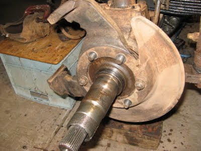
Refitting the Spindle, drivers side

Grease the rear oil seal bearing surface and clean out the spindle nut threads.

When fitting the hub to the spindle, have the greased up outer bearing and the hex spindle nut ready to go. Otherwise, when you fit the hub with only the rear bearing in place the hub might slip down the spindle when you let go.

I was tempted to put bearing retaining compound on the bearing cup surfaces to prevent the original problem of the bearing cups rotating on the spindles, but there is so much grease around that I doubt that the retaining compound could do it's job effectively. With rebuilt and reground spindles it shouldn't be necessary anyway.

The spindle nuts should be tightened to 50 ft-lbs, spun a few times to seat the bearings and circulate the grease and then backed off about 45ยบ before fitting the lock washer and outer lock nut. Pre-loading is essential for tapered roller bearings so they share the load equally. If there is any free movement, they are too loose. On the road I check the temperature of the hubs frequently to ensure they are not getting too hot. Warm is OK due to the brake heat, but if one is appreciably hotter than the others, something is wrong.

[There are some very useful tech notes on bearing problems and installation at the Timken site hereand here].

Fitting the lock washers can be a tricky task. Bend 2 tabs in towards the bearing, being careful not to go too far or you can damage the bearing cage. I used a rod formed from the tapered end cut off a tent peg to do this. Bending 2 tabs outwards on to the lock nut is even more difficult. I made a small tool using another tent pen with a sharp bend on one end (more than 90ยบ so it won't slip off) and threaded the other end. Using a breaker bar with a hole it it, I slid the tool in behind the tabs and levered against a nut fitted on the threaded end. Once the tab has bent slightly, I used a square shank screwdriver to lever them flat by twisting it with a wrench on the shank.

[In the US, there are more sophisticated (but expensive) locking devices described here and here].

Epilogue

The rest of the rebuilding process (free wheeling hubs, tie rod ends, steering damper, brakes, wheels, diff cover/oil etc.) should be fairly straight forward, but as with any major project, check if there are any bits left over and check that everything is reconnected, tightened, greased or refilled.

On it's first test run, there was no evidence of the original vibration which kicked off the whole axle reconstruction program in the first place, and the steering seemed a lot smoother, although there's no logical reason for that other than the greased joints. I ran the Oka in 4wd for a while, but with the hubs unlocked, to allow oil to circulate through the diff components before any load is applied to it.

This has been quite a long and complex rebuilding process and ironically, there will be almost nothing to show for it at the end, except peace of mind.

However, it is not difficult or mechanically challenging or even very expensive, there's just a lot of it.

Thursday 10 September 2009

Vibrations from the Front Axle - Part 1 of GARP, The Great Axle Reconstruction Project

Over the past few months our Oka developed an occasional but worrying vibration at 60-70 km/h from what appears to be the front axle/wheel area, possibly from the passengers side. Braking or turning or de-clutching didn't seem to affect it and it was there in 4wd and 2wd. 


At first I thought it was just knobbly tyres on a rough road surface (that's what it sounds like), or the brake callipers (see this article, which is relevant to Oka brakes), but I thought I had fixed any calliper/pad rattles and looseness. Then I thought maybe a wheel bearing shell might be jamming occasionally and rotating on the spindle, but why only at one speed? Investigating that possibility is a rotten job, with freewheeling hubs and brake callipers to remove, lock washers, messy grease etc. and anyway I had checked/greased the bearings last year and recently had the wheels balanced.


"Tim" on the Oka Owners Group website suggested that the vibration might be caused by a worn steering damper. I haven't investigated that yet, since everything is now in pieces, but it is a possibility, although I don't quite understand how it could occur or why turning the steering wheel didn't affect it. I had considered ignoring the problem completely and just turning up the radio, but after checking the steering rods and swivels, springs and shockers, and any part of the bodywork which could have been vibrating in the wind, I bit the bullet and took the wheel hub assembly to pieces.


Pic 1. The groove and ridge ringed on the spindle shaft. (Click to enlarge)
It only took an hour or so to get to the heart of the problem, the outer bearing shell had indeed been rotating on the spindle and worn a groove (about 0.5 mm deep), so that the bearing was a fairly loose fit on the shaft. A ridge had also developed which prevented it from sliding freely, and this would affect the bearing pre-load adjustment as well. See ringed area on Pic 1.


What to do about it was the next question. If we were in the US, a replacement spindle for a Dana 60 axle would be easy to find (and cost around $US100-150), but in Oz, from Oka the price was out of this world ($600, each).

So I investigated a repair process. I found a company in Adelaide (Adelaide Grinding) that would deposit a coating of metal on the shaft (by replating or metal spraying) and then regrind the bearing surfaces to their original dimensions. Since I wanted to do this only once, I also had the inner bearing surface treated at the same time, even though it wasn't as badly worn. Even better, the total cost was less than a quarter of the new spindle price.
While I was at it, I took the other spindle off and, not surprisingly, it was in a similar state of disrepair so I had that repaired as well.
Pic 2. The repaired spindle. Bearings are a good tight slide fit on the reground shafts.
I will also replace the oil seals at the rear of the spindles and the seals on the drive shafts to keep water out of the bearings. The needle roller bearings which centre the drive shaft were very gunged up but not badly worn, so a good clean out and regrease is all that is necessary.
The 6 nuts holding the brake calliper and spindle on to the steering knuckle weren't as tight as I was expecting, considering that they support the whole weight of the vehicle, plus traction and braking loads as well, so I will Loctite them and torque them to 60 to 70 ft-lbs. The torque setting for Dana 60 Spindle nuts is 65 ft-lbs (88 Nm) and I assume it would be the same for Dana 70 rear axles.

I did consider rotating the spindles so that the previously worn section was now having a rest and a new section could take up the load. However, that plan came to nought when I discovered that the spindle bolt holes are not symmetrical and the spindle will only fit one-way. It is possible to interchange the left and right side spindles however, which might have a marginal benefit.

The Low Point Approaches...

While the hubs were off being repaired, I took the opportunity to change the front diff oil.
So I loosened the diff cover bolts to let the oil out (for there are no drain plugs on these axles) and heard a "clink" as something dropped into the tray. Rather than dirty my fingers, I got my magnetic wand out and stirred it around in the dirty oil. When I removed it there was part of a gear tooth attached to the end.

My heart sank as I knew what that would mean, and sure enough, when I removed the cover and turned the inner gears around there was one with part of its tooth missing.
Pic 3. Toothache in the differential.
Had there been a drain plug I would never have noticed the missing tooth, but since I now knew about it, it simply couldn't be ignored. From a pragmatic perspective, there would never be a better opportunity to repair the diff, as removing it was only 4 bolts away, since the hubs, wheels, brakes and drive shafts had already been removed.

This was also the unexpected opportunity I had been waiting for to replace the inner axle oil seals which are only accessible when the diff is removed. Muddy water from Kimberley creek crossings had got into the diff housing past the worn seals and laid at the bottom of the housing. This had caused surface rusting and pitting on some of the crown wheel teeth and bolts, since the front diff is stationary for much of the time. Mine site seals are available to block off the openings to the axles tubes, but the advice I received is that they tend to trap water in the tubes leading to worse corrosion problems, and it's better to allow them to drain open to the atmosphere.

Removing the diff was surprisingly easy and after freeing the 4 bearing cap bolts, it just about fell out, or would have done, except for the steering tie rod which crosses right in front of the diff cover. This tie rod can't be easily removed since it hits the bottom of the springs before the tie rod ends can be lifted free from the steering knuckles. Luckily, after a bit of manoeuvring I managed to turn the diff carrier assembly on its side and slide it out under the tie rod. If you've already loosened one or both tie rod ends, it would probably help to clamp the rod up as high as possible to keep it out of the way. I just hope putting it back will be as easy.

So, buoyed with the negligible enthusiasm which stems from having reluctantly removed the diff, I went on the hunt for replacement gears, and once again in the US they are easy to come by, but not so easy in Oz. They are available from a few auto parts companies specialising in American vehicles, (eg here and here) but to be sure I got Oka compatible components, I acquired a second hand set from Paul Nott at East Coast Oka in Melbourne (which turned out to be a lot less worn than my original set). With some replacement oil seals on the way from Oka in Perth I am now able to start GARP, the Great Axle Reconstruction Project.

GARP Part 2 documents the axle reassembly phase from this low point to being ready to roll.

Don't you just love it when the manuals say "To reassemble, simply reverse the disassembly procedure"?