Welcome to David and Janet Ribbans blog

We live in Adelaide, South Australia and enjoy travel in the Australian outback in our Oka 4WD motorhome, hence the blog title.


To quickly locate any of our more than 80 travel and technical articles, use the drop down menus below or scroll down the lists in the right hand sidebar. But please read the disclaimer first, we've tried to be accurate and current but things can change...
You can also visit the official Oka 4WD website here.

Pandora Web Archive


We're now honoured to have our blogs archived
on the National Library of Australia's Pandora Web Archive.
Bookmark this link to the archived version in case anything ever goes wrong with Google, or I accidentally hit "Delete All" in a fit of pique. The drop down menus above might not work in the archived version but everything else should...
Showing posts with label Electrical. Show all posts

Sunday, 30 October 2011

Starter Solenoid/Armature Failure Analysis

Starter Motor Failure

Our starter motor failed in mysterious circumstances at Eucla, half way across the Nullarbor Plain. We'd stopped to use the facilities at the Eucla Roadhouse and afterwards, the starter motor refused to function.

The solenoid on the starter motor had been giving intermittent trouble for a couple of years and usually tapping the start relay connection was enough to get it going, but not this time. I replaced the solenoid but the motor was still faulty so we eventually assembled a working one out of spare parts and found that a replacement armature was also required to get it going.

Further analysis on the faulty components was obviously required after we arrived home. This is it.

Solenoid Failure

In Eucla I took the solenoid off and checked it electrically. Not surprisingly one of the windings had failed internally.

Since these are not repairable items (at least, not without a lot of effort and desperation) we ordered a new one which took a couple of days to be delivered from Perth. In the event that didn't fix the starter problem and we had to wait until we could bump start the Oka and travel on to Coolgardie, without switching the engine off, where I could fix or replace the motor.

The second, concurrent, problem was a faulty armature, which turned out to be a winding fault, rather than excess commutator wear (which would have been simple to fix). Why and how we could have 2 problems which occurred at the same time is still a mystery, unless the solenoid was in one of its in-between failure periods and it was actually the armature which failed first. I guess we'll never know but it did delay us for a few days, luckily right outside the Eucla Motel.

Opening up the Solenoid

The starter solenoid is assembled into a steel cylinder, the top edge of which is peened over during the manufacturing process to hold the contactor plate in place, so it can't be easily be disassembled.

Electrical operation of a starter solenoid is explained in this useful article.

I first unsoldered the winding wires from the terminal posts (there are 2 wires on one terminal) using a solder sucker and desoldering braid to remove the solder. The thinner wire came completely out indicating a broken or fused wire in the hold-in winding. Then I cut through the skin of the cylinder near the contactor using a hacksaw and removed the internal components.

b5ad6dc9-1-2011-10-29-18-20.jpg

Where I cut the solenoid cylinder

689e6faa-2011-10-29-18-20.jpg

The contactor removed after cutting though the cylinder

The windings are wound around a plastic former on a steel base plate which is held in place by a large circlip.

4264264d-2011-10-29-18-20.jpg

The fused hold-in winding and circlip holding the coil base plate in

After removing the circlip and sliding out the coil assembly, it was immediately obvious that there had been a burning event and both windings were burnt black at the terminal end. Although the hold-in coil had failed, it was unclear whether the thicker pull-in winding had overheated, causing the thinner hold-in winding to fail, or vice versa.

6dacd5cb-2011-10-29-18-20.jpg

Windings removed

87112560-2011-10-29-18-20.jpg

43c7c853-2011-10-29-18-20.jpg

The burnt windings.

The thinner hold-in winding is wound over the top of the thicker pull-in winding, separated by paper insulation.

Solenoid Repair Possibilities

The solenoid is a fairly simple electrical device and if necessary it could be rewound and reassembled by cutting out the burnt sections of wire (the insulating enamel may have been damaged by heat causing further short-circuits) and rewinding them. The windings both have around 100 turns on them so a few turns missing would not affect operation appreciably. The cut off cylinder could be repaired using a hose clip, tie wraps or similar to hold the contactor plate in place.

240b7447-2011-10-29-18-20.jpg

Pull-in winding after removal of the hold-in winding

Although the solenoid could be repaired if the situation was really desperate enough, it's probably a better choice to carry a spare at around $100 and save all the potential angst.

eed2bb96-2011-10-29-18-20.jpg

Contents of the solenoid

"To reassemble, simply reverse the disassembly process"

Causes of Failure

There was no obvious mechanical or electrical reason for the winding to fail, but possible causes are:

  • Prolonged engagement of the starter motor, allowing the windings to heat up to the point where the insulation breaks down, causing a partial short circuit and leading to eventual winding failure, or
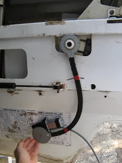
  • Heat from the exhaust system which runs nearby, aggravating the internal self heating of the solenoid windings and leading to the same result. This is most likely to happen when restarting an already hot engine (which coincidentally is exactly what happened to us in Eucla), or
  • Shit just happens when you least expect it.

2bc40875-2011-10-29-18-20.jpg

The solenoid on our Oka is very close to the exhaust

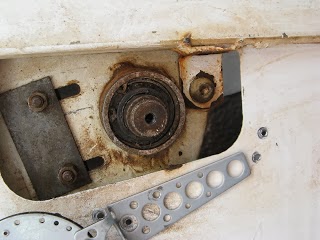
Using Iskra starters (and possibly other makes), there are 2 frame types with different locations for the starter solenoid:

  • on the side of the motor (which is close to the exhaust pipe on our Oka), or
  • below the motor where it's more exposed to impact damage (but no more so than the engine sump would be).

There is the merest possibility of the front drive shaft or its capture hoop touching the solenoid in the lower position at maximum axle articulation, but that seems most unlikely to happen in practice as the bump stops/airbags would have to completely fail to do their job.

94d0145a-2011-10-29-18-20.jpg

Solenoid located on the side of the motor, like ours,

Iskra IM527

b267649b-2011-10-29-18-20.jpg

Solenoid in the lower, but more exposed location,

Iskra IM315

The only difference between the motor types is the position of the solenoid and therefore the battery cable runs.

b10663d6-2011-10-29-18-20.jpg

A solenoid in the lower position on an Oka

My preference now is for the lower location since impact damage would be rare and obvious, rather than the side location (which is where ours is currently) where the solenoid is exposed to continuous exhaust heat, so I shall be changing mine for the lower type and fortunately I have acquired a spare frame of this type. For starters with the solenoid near the exhaust, I recommend fitting a heat shield of shiny aluminium, or even reflective tape, between them to reduce the effects of radiant heat.

Armature Problem

Well I've now done some analysis of the faulty armature.

I started by buffing up the commutator to ensure that the brushes would seat properly and eliminate that as a problem. I didn't have a lathe big enough to hold the armature so I made a simple stand by clamping the bearings on each end in small vices clamped to the workbench. I then turned the armature by hand and used a flat file to dress the commutator. [I did try using a cordless drill and belt to turn the armature but too many hands were needed to hold it steady and it only took about 10 minutes anyway].

b09a4c79-2011-10-29-18-20.jpg

Rudimentary lathe assembled to dress the commutator

Once the armature was smooth and flat, I rebuilt the motor and tested it on a car battery using jumper leads.

The motor still didn't turn but a whiff of smoke indicated where the problem was: 2 adjacent segments are presumably shorted internally and a burn mark was evident on the end of the commutator where the smoke appeared.

a99ea0c9-2011-10-29-18-20.jpg

The burn mark where the smoke appeared from.

To confirm that this was not caused by internal short circuits in the area of the brush plate, field coil connections and/or fixing bolts, I removed the end cover and held the motor in a vice while applying voltage.

The motor still didn't turn but it put up quite a light show to confirm there is indeed an internal problem with the armature, irrespective of its rotational position.

9165fd32-2011-10-29-18-20.jpg

A light show but no movement, and I was wearing eye protection.

Conclusion

So the armature would seem to be completely cactus and probably not worth repairing. But it also confirms that our problem in Eucla was indeed caused by 2 concurrent problems, the failed solenoid and an armature fault, although I now suspect that the armature fault was the primary show stopper.

The fixed field coils seem to be very robust so should be more reliable than rotating/sparking parts:

  • They don't move,
  • They're made of thick, solid copper bars,
  • I have a spare set.

Brushes can be replaced and I have a spare set, plus brush plate.

Solenoids can be replaced (I now have a spare), bypassed or even fixed on the side of the road but not the armature.

So the question now is whether to acquire a new or s/h (spare) armature or a whole new (spare) starter motor or get this one repaired.

Or do nothing and hope the existing one will last for ever.

Sunday, 14 August 2011

Minimum Electrics to Start the Engine (Injector Pump Solenoid Fix)

On an Oka, there is only one critical electrical item which keeps the engine running or not, and that's the fuel cut off solenoid at the back of the injector pump. (Bosch call it the ELAB, electronic shut off device. This Bosch Instruction Manual is a very valuable resource on the VE pump).

As long as you can start the engine (maybe by bump starting it if you have no battery power or the starter has failed), that solenoid wire with 12v applied is the only electrical thing needed to keep it running and a even small 6v lantern battery would probably do.

Minimum Electrics to Start and Keep the Engine Running

Even if all dashboard "ignition" functions are disabled, connecting up the fuel cut off solenoid to 12v and hot wiring the starter motor to the battery (or batteries) should start the engine (in neutral of course with the park brake on since you'll be under the vehicle). The key is still required to unlock the steering though.

Connect the Start Relay connection on the starter relay body (a small terminal between 2 large ones) to the battery +ve to engage the starter gear (only a thin wire is required), and remove it when the engine starts. (One of the large terminals will be a battery +ve connection so only a short wire is needed, even a screwdriver would work).

If there's only a click, or nothing at all, the battery wiring is suspect so you may also need to use a thick jumper lead to connect the battery +ve to the main starter motor terminal (which is probably on the starter relay body, not the actual starter motor, follow the (red) wiring from the battery), but it should already be connected. The lead on our starter motor body is actually a (black) ground connection.

Also check that the battery -ve is effectively connected to the chassis or frame of the starter motor using the other jumper lead.

Disconnecting the fuel cut off lead will stop the engine (or it can be stalled in a high gear by gently letting out the clutch with the brakes on).

If the engine rotates but doesn't start, it's a fuel problem (or less likely, a major mechanical fault) and that could be the solenoid. But it could also be the lift pump, or you could be out of fuel, or have air or a blockage in the system so check out these and all other possibilities before accusing the solenoid.

What if the starter fails?

Another obscure fault we have had is an intermittent winding connection inside the starter solenoid on top of the starter motor body. This can prevent starting on an otherwise healthy vehicle and are not repairable items so a spare would be a wise investment (about $100). Pity we didn't have one when ours failed, we had to have one shipped from Perth to Eucla.

81bdf317-2011-08-14-08-57.jpg

The solenoid with the dodgy connection, after I reflowed the solder to try and fix it.

The contactor inside can still be used to connect the starter motor by pressing the plunger on the other end

A possible bush repair in this case is to:

  1. remove the starter solenoid (three long philips head screws on ours and you'll probably need to remove the starter from the engine first),
  2. use a mechanical method (eg a rod with a slotted head tie-wrapped to the motor body) to pull the gear lever inside the housing backwards away from the housing (to engage the starter gear) and
  3. ensure the gears are in neutral and connect the starter motor connection to the battery +ve manually, using the internal solenoid contactor (and pressing in the internal plunger to bridge the contacts), a high current (300A+) relay (like the one for paralleling dual batteries) or or even a thick jumper lead. Connecting  batteries in parallel will help to drive the starter motor.

Jumper lead connections may spark a lot and weld themselves together so use a very thick steel bar to absorb the heat and wear glasses (using the solenoid contactor or relay captures any sparking), but the motor should now turn over and start the engine.

Quickly remove the connection or release the plunger as soon as it starts, and push the rod so the solenoid gear lever moves forward into the housing, disengaging the starter gear. The rod can be tie-wrapped to the motor body so that the gear can't accidentally re-engage.

c09000b0-2011-08-14-08-57.jpg

The gear rod pulled forward to engage the drive

You would need to do this each time you need to start the engine so it's only an emergency fix, so leave the engine running during all short term stops and think about restarting options before switching it off. Doing this is a busy car park or on the road side would be potentially dangerous or frustrating.

If all else fails, the Oka can be bumped started quite easily. With a couple of people pushing, the Oka will roll quite well on a hard surface and 5 tonnes of Oka has sufficient energy to turn over the engine, even when moving slowly.

Checking the Fuel Cut Off Solenoid (not to be confused with the Starter Motor Solenoid)

I have rarely read or heard of a failed fuel cut off solenoid, whereas broken wires and terminals are commonplace, so check that it really is the solenoid first, before removing it. It should have a low resistance to ground, a few ohms (probably around 10 to 20 Ω, check it by connecting a 5W globe in series to +12v, it should glow if the solenoid coil is OK). If you can hear it click when voltage is applied it's probably OK too.


What if the Solenoid has Failed?

If the cut off solenoid itself really has failed (other than a broken terminal screw, and you could tape a wire to it to maintain contact), the engine can't start. I did think that removing the solenoid and using a magnetic pick up wand to engage the valve may work. However the solenoid valve also seals the rear injector port so removing it would allow fuel to leak out, probably under pressure, so that trick won't work. (See this photo of a disassembled solenoid valve and its location). In this case replacement or modification (see below) of the solenoid is the only answer. This is now on my list of "Things To Do If Desperate".

Fixing the Solenoid

One good suggestion I have seen (thanks to RedZerOne) is a simple modification to a failed solenoid to get the engine going:

"When mine went out two years ago, I gutted it rather than replace it. To do this, remove the solenoid from the VE pump [edit: 15/16 inch spanner] and remove the plunger and the spring from inside the solenoid. Double check in the pump and solenoid that there's no debris and reinstall the solenoid. This will allow the engine to have fuel constantly. It'll operate the same as if you had a working solenoid, the only difference is that in order to shut off the engine, you'll have to manually stall it out. I've been doing this for two years now with no problem."

dsc05410-2011-08-14-08-57.jpg

Remove the spring and plunger and reinstall the solenoid

Photo courtesy http://bricofoy.free.fr/phpwebgallery/

Note, no electrics to the pump are required after this mod and the fuel will be permanently on, which doesn't matter except that the engine won't stop and would have to be stalled. However getting access to the solenoid might require removal or loosening of the top section of the pump, but if you're desperate enough anything goes.

[In fact if you can bump start the Oka after parking on an incline (I'm not sure how easy this is with a diesel, try 2nd or 3rd gear), you wouldn't even need any batteries after this mod to the solenoid. Caution, if you ever try this without batteries, disconnect the alternator first to avoid generating high voltages after the engine starts which could damage any electrical equipment. The batteries normally constrain the voltage to around 14v, even dead ones, but an unloaded alternator can generate up to 100v at very high power and can even be used as a welding supply].

dc993818-2011-08-14-08-57.jpg

This the solenoid location on our injector pump.

It looks inaccessible, but with a 15/16th spanner or shifter it should be possible to remove it.

087f8f82-2011-08-14-08-57.jpg 

The solenoid is on the right, with the top of the pump removed.

It shouldn't be necessary to go this far, I was replacing the throttle shaft seal when this photo was taken.

Friday, 12 August 2011

Electrical/Electronic Mods to our Oka

Being an electronics engineer it was inevitable that I would make and installed lots of electrical/electronic modifications and additions to our Oka.
None of these mods affect the basic functionality of the Oka, in fact there is only one essential electrical item which keeps the engine running or not, which is the fuel cut off solenoid on the injector pump.
As long as you can start the engine, the solenoid wire with 12v applied is the only electrical thing needed to keep it running. See this post for the minimum electrics to start and keep the engine running.
Electrical Mods to our Oka (** indicates my own design/construction)
Mods which relate to Driving
  • Smart alternator regulator for our 120A alternator (Sterling AR12VD)
  • Triple batteries with automatic charge connection and manual paralleling switches**
    • Supercharge Gold MF95D31R (760 CCA) starter battery
    • 2 x Supercharge MRV70 (105 AH, 760 CCA) Allrounder (Starting and Deep Cycle) house batteries
  • Solar panels (200W, 10 x 20W) and multiple battery charge controller**
  • Charge monitoring display system (current and voltage)**
  • Start Lock Out system**
    • Prevents the engine from being started until an enable button is pressed, after the ignition is turned on
    • Fitted with an emergency engine stop button
  • Reversing and forward facing (for seeing over crests) cameras and 9 inch LCD display
  • Wiper delay system**
    • 6 delay periods
    • 1 or 2 wipes per cycle
  • Dashboard electronics**
    • Voltage and charge current meters switchable to each battery (LCD and LED)
    • GPS PSU
    • Turbo Timer
    • Headlight/Step/Vent/Pump "Left On" reminder system
    • Laptop PSU for moving map system**
  • Remote central locking doors**
    • Fitted to all 3 doors, with interlocks so that any internal door handle can lock and unlock all doors**
  • Electric windows on both front doors**
  • Remote switching of fridge dc**
    • Allows fridge to be switched off from cabin when stopped (eg for fuel), to reduce battery load. Normally the fridge runs from 240v ac via the inverter while travelling as it's more efficient than dc, less cable losses. Solar panels provide power when the alternator is not charging
  • Automatic inhibit of Water Pumps**
    • Inhibits pumps when the ignition is ON, to prevent accidental pumping out of water if a pipe leaks or breaks while travelling
  • Diesel Transfer Pump to transfer fuel from rear to side tank
Mods which relate to the Motorhome
  • System switch functions for all rear electrical equipment**
    • Pumps, Lights, Fans
  • Water Level Meters for both main water tanks**
  • Fridge/freezer monitor and alarm system**
    • Display of fridge and freezer temps
    • Over temp and flame failure alarms
    • Indication of energy source (ac, dc or gas)
      •  Note: Fridge is normally powered from ac inverter while travelling, it's more efficient than powering from 12Vdc
  • Fridge Fan to circulate cold air, stops when door is opened**
  • Fridge LED Lights which operate when door is opened**
  • Window Fans to cool us at night (speed controlled from quiet breeze to gale force)**
  • 300W Sine Wave Inverter (Jaycar) with RCD (later removed since it couldn't handle the vibration)
  • Soldering Iron, 24v 60W, temperature controlled, runs from dc-dc converter**
  • Drill battery charger, 24v, microcomputer controlled
    • Runs from same dc-dc converter as soldering iron
  • Computer systems
    • GPS moving map system based on MacBook Air, USB GPS and Oziexplorer running under VirtualBox and XP
    • 17 inch LCD display mounted on engine cover
    • NextG Phone/Modem, (plugs into MacBook), with options of external whip and Yagi antennae
    • 2 x 40W channel HiFi system switchable from radio to computer**
  • Smoke Alarm inhibitor**
    • Prevents activation while cooking. Manual reset or automatic reset after 40 minutes
  • NiCd/NiMH Battery Charger (up to 10 AA and/or AAA batteries at once)
  • Rechargeable Dolphin LED Torch using 8 1/2 W LED's and 6v SLA battery**
  • Dustbuster converted to run from 12v (internal 12v to 6v switching converter)**
  • HF Radio, (Codan 7727 with VKS737 frequencies)
    • Modified to receive ABC and BBC shortwave broadcasts
    • Allows transmit/receive on the 40 meter (7 MHz) amateur band (call sign VK5MDR)**
    • Frequencies can be selected via an external VFO**
    • Allows broader range of emergency frequencies
    • Jenal SC2 microphone fitted to allow direct RFDS connection via Selcall though VKS bases**
    • Tapped whip and 9m Super Rod antennae
  • SW Battery Radio
  • LED Lights**
    • External LED camping lights
    • Internal LED lights
    • Automatic porch/step lights (comes on at dusk when door is opened)
  • Fridge dc low voltage cut off**
  • Roof Vent fan speed control**
  • Evaporative air conditioning controls**
    • Controls small evaporative a/c for use when the engine is off
    • Provides automatic shots of water to keep the evaporator pads damp instead of a continuous supply, to save water. Uses a timer to control a solenoid valve from the pressurised water supply
Future Planned Mods
  • Microcomputer controlled turn indicators/hazard flasher**
    • To accommodate variable loads with future LED lighting systems
    • Static or “Knight rider” type displays
    • Various Left/Right/Hazard “ringtones”
    • Auto volume control (louder with more ambient noise/radio on)
    • Brighter internal flasher LEDs
    • LED and wiring fault detection
    • Auto L/R reset after 15 sec (adjustable)
    • Warning sound, horn or silence on Hazard flasher
    • Hazard flasher can drive rotating lamp and/or alternating L/R or F/R indicators
    • Hazard can flash all lights (Headlights/Stop/Tail/Indicators) alternately to even out battery load
  • Air Conditioning controller**
    • To display internal and external temperatures
    • To control the fans, compressor and front/rear temperature balance

Sunday, 16 March 2008

How to add Power Windows to an Oka

IMG_1431.JPG-2008-03-16-07-21.jpg

This blog describes how I added power windows to our Oka.

Since the Oka front door windows are belt driven, very heavy and different to other cars, I thought that fitting power windows would be difficult, if not impossible, but it wasn't impossible.

There are no doubt other ways to do it (there are many American websites selling power window lifters, or regulators as they call them, of many different types for all manner of vehicles, but not Oka of course), but this way was quite simple and effective.

I bought a 2 door power window kit from Rapid Electronics in Melbourne via ebay for $95 plus $20 shipping. There are other suppliers and types available as well but the kits are not available all the time. However they reappear regularly for around the same price. Delivery was very quick and most kits seem to use the same rectangular silver drive motors now, which are claimed to be "high power", which is encouraging.

How do they work?

To see how they work, visit these sites. Installation Guide #1 and Installation Guide #2.

OK, so they are shown being fitted to an old Holden, but the principles and operation are the same, and they show far more detail than I was intending to.

I have not yet determined the longevity of the motors and drive assemblies on an Oka, but on short term testing they seemed OK, even though the motors do take a fair whack of current (10+ Amps, over 120 watts, when closing the windows) and get pretty hot.

Fitting them to an Oka

To fit them to an Oka means the following operations:
  • Remove the door handles, grab handles and window winders from both front doors.
  • Remove the christmas tree fixings and remove the plastic trim
  • At some stage you'll probably want to remove the door stays too, either to be able to open the doors further or when they get in the way.
Since the Oka windows are pretty heavy at the best of times, you'll need to lighten the load as much as possible by:
  • Releasing the tension on the friction slide mechanism.
  • Greasing the window slide channels on both sides and the belt slide channel. I used lithium grease but there may well be better products for this purpose.
The window should wind up and down freely using the original window winder, if not, the electric motor drive will have a tough job closing the windows.

I used to have the slide friction pads tightened up as much as possible to stop the windows from sliding down and rattling on rough roads. With the electric version, the worm drive on the motor unit should prevent the motor from being turned by the window and keep it tightly shut. We'll see.

[Post trip note: Yes, the worm drive DID prevent the windows from rattling or sliding down. This was after a 14,000 km outback trek including the Anne Beadell Highway, Great Central and Sandy Blight Junction Roads.]

Locating the Motor Drive Assembly

Fitting the power window motor assembly took some trial and error. I tried 3 or 4 different locations:
  • Option 1: In the well above the grab handles, or in the cut out near the door catch.
IMG_1391.JPG-2008-03-16-07-21.jpg

In the well didn't work out since the motor, although thin, is too fat and fouled the door trim and/or the window glass, although the belt is nice and straight. In the cut out near the door catch would have worked fairly well with the belt skirting around the bottom of the door handle bracket.
  • Option 2: In the space just above the floor but below the door trim.
This would have worked mechanically but would protruded into the cabin and would have needed a cover made.


IMG_1390.JPG-2008-03-16-07-21.jpg

  • Option 3: In the cut out near the door hinges.
IMG_1393.JPG-2008-03-16-07-21.jpg

I thought this would foul the window glass when wound down but it didn't, and proved to be the most suitable location.

The door trim fits back almost perfectly, except for a slight bulge where it goes over the drive belt beneath the door stay. This is almost unnoticeable.

The motor drive belt is designed to be bent around as long as the centres of the motor and drive cog are not less than 30o mm apart. In this configuration they end up about 400 mm apart.
  • Option 4: I have power door locks fitted to our Oka, bits of which fill up the other cut out near the door catch, otherwise that area might have been a possibility too, with the belt skirting beneath the door handle bracket. Fitting the cables from here would be more difficult.
Mounting the Motor Drive Assembly

Mounting the motor drive assembly and securing the drive belt cog is not difficult with the items supplied, just a bit of cutting, bending, drilling and screwing. Most of the other bits in the kit are intended for use in cars where the noise and vibration of the motor might be distracting. Not a critical Oka concern.

I fitted a piece of rubber sheeting between the motor body and the door skin too avoid any scuffing or noise as the motor vibrates. It's no noisier than a normal car power window.

The drive belt will foul the body of the door stay slightly as the door closes, so a small strap was fitted to pull the belt closer to the door skin and out of the way of the door stay.

If you locate the drive motor here, drill the 12mm cable hole in the door through the cutout before mounting the motor.

Assembling the Drive Mechanism

Assembling the drive cog on the window winder was also easy, at first.

A large number of different cogs, gears and spacers are provided in the kit to suit different cars. We don't need any of them.

With the window winder removed, the shortest of the large nylon cogs fits neatly over the splined shaft, and the drive belt cog from the motor slips over the nylon cog to drive the window winder up and down. In theory.

Having assembled the cogs and mounted the motor and drive belt, I hooked up a 12v source and tried it out. It worked reasonably well on the drivers door, but when I tried it on the passenger door, a problem arose. Over the years, the tops of the splines had worn down so when the window reached the top and stopped, the power of the motor continued to turn the drive cog which slipped around, wearing off the peaks of the nylon cog on the worn down steel splines. If this didn't happen now, it was certainly going to happen sometime soon, so another approach was needed.

Soft nylon turning a steel splined shaft at high torque is not a good match. What was needed was a mechanical locking method to tie the splined shaft to the nylon drive cog. (I figured that there was less torque on the teeth of the larger drive belt cog from the motor (twice as big, therefore a 1/4 of the torque??) and so it was going to last longer, so I focused on the smaller cog).


IMG_1394.JPG-2008-03-16-07-21.jpg


First I removed the splined shaft from the window winder mechanism by releasing the (quite strong) circlip holding it in and removing the plastic spacer and shaft. It was easier than I though it would be.
(Note: When replacing it, ensure that the ends of the internal spring are correctly located in the shaft cut-out.)

Then I made a round steel plate the size of the nylon cog (and so the end of the drive belt opening would slip over it) and drilled a 5mm clearance hole in the centre. (The original window winder handle is held on to the splined shaft by a 5mm bolt).

I drilled a series of 2mm holes in the plate, 4 around a small circle which coincided with the end of the splined shaft, and 4 which coincided with the ring of the nylon cog. I then fitted the nylon cog to the splined shaft and cut it down flush with the end of the splined shaft.


IMG_1403.JPG-2008-03-16-07-21.jpg


After mounting the plate on the splined shaft with a 5mm bolt, I drilled through the holes in the plate using a 2mm drill, into the end of the splined shaft to a depth of 6mm, and right through the nylon cog.

This is best done on a pedestal drill for stability and accuracy and after drilling the first hole, drop a 2mm bolt in it to stop the plate from rotating while the others are drilled.

Mark the plate and shaft so that it can be replaced in the same orientation, unless you can achieve perfection in drilling accuracy.


IMG_1408.JPG-2008-03-16-07-21.jpg


Having made one plate that fits, it's a good idea to use it as a template for the others and drill them before cutting and rounding the plates. It makes them easier to handle.

They don't actually have to be round, square or octagonal would do, so long as the drive belt cog can fit over it and there is room for the 2mm bolts. Round just seemed a neater solution. There was no need for nuts on the 2mm bolts (there's no space anyway) as I held all the bolt heads in place with another round plate, via a clearance hole in its centre, with a 5mm bolt. Like a sandwich. A blob of Selleys All Clear on the bolt threads would reduce any movement as well.

Using 2mm bolts, (6mm long into the shaft and 8-10mm long through the nylon cog), I assembled the plate to the splined shaft.


IMG_1412.JPG-2008-03-16-07-21.jpg

pbp-2008-03-16-07-21.gif
A blob of Selleys All Clear on the bolt threads would reduce any movement as well.


IMG_1415.JPG-2008-03-16-07-21.jpg


The whole assembly is now mechanically locked together with the 8 x 2mm bolts acting as locking pins.

The plates were painted to avoid corrosion before final fitment, as were the holes drilled in the door skin.

Once the system is operating satisfactorily, I shall Loctite the 5mm bolt in place to avoid anything coming loose.

2mm bolts are not the only way of achieving this fix, roll pins or any small steel pins would do, but bolts with heads on are more easily held in position and they do need to be small, there is not a lot of room to move. Small self tappers might also work but they would probably come loose. 3mm bolts might just fit but would be trickier to position accurately.

2mm nuts and bolts are available from Dick Smith and Jaycar Electronics.


IMG_1405.JPG-2008-03-16-07-21.jpg


4 bolts on each section are probably a bit of an overkill, but it looks symmetrical and strong, and works well.

When the mechanism is fitted finally, there is thin spring/circlip supplied in the kit which must be slipped over the larger nylon cog into a groove, to tie it to the drive belt cog, otherwise it could slide off while operating.

I found in practice that the thin spring came adrift during operation, and I couldn't see any way that the drive belt cog could slip off, it's held on pretty tight by the mounting brackets, so it's probably not essential.

With this mechanical locking system in place, when the window gets to the top, the mechanism now stops with no slipping. However, in this position the motor is stalled and will be drawing maximum current, so it must not be held there for more than a second or so to avoid overheating (and eventual burn out) of the motor. You would hope that the motor design takes account of this situation with a thermal cutout or similar, but how can we be certain?

Originally I was intending to leave the window winder in place to enable some manual assistance to be provided to raise the window if the system struggles, or in the event of a failure to the system. However this is not practical since if the system fails though an electrical fault (eg a blown fuse or burnt out motor, a likely cause with heavy windows), the torque from the worm drive on the motor shaft would prevent the window winder from operating, and with my mechanical shaft locking in place, it can't be easily fitted on anyway. So in the event of either electrical or mechanical failure, the mechanism would have to be removed and the original winder assembly replaced. (Note to self: Mustn't forget to take them with us on our next trip).

Wiring the Electrics

The kit comes with a cable harness and 2 switch assemblies, a double switch for the drivers door to operate the windows on both doors, and a single switch for the passenger door.

Switch housings are provided which can be screwed to the door trim from the inside in the most comfortable position. Alternatively, the switches could be mounted directly in rectangular cutouts in the door trim, if the housings take up too much space. However, there might not be sufficient space behind them for the cables in that orientation.

Cables will need to be fed though the frame of the door and the Oka body to allow connections to be made to the motors and switch assemblies. This will require 12mm or 1/2 inch holes, with grommets to protect the wires.

Drill a hole in the end of the door first through the cutout where the motor will be mounted. A corresponding hole is required in the Oka body about 75mm lower (or higher) than in the door, to provide room for the cables to twist without straining as the door opens and closes.

I was not convinced that the cables supplied would be man enough for the job, especially when raising the passenger window from the drivers side. The wires carry quite high currents across the vehicle and require to be fairly meaty cables.

The main culprits are the White, Blue and Blue/Red cables running across from the drivers door switch to the passenger door motor. They carry the full motor current when raising and lowering the passenger window across all the way from the drivers side, even when the passenger door switch is operated. The positive current to the passengers door is supplied by the White wire which is spliced into the Red wire, which is the primary +12v supply. With the original cables, I was losing about 4 volts across the cables during winding (12v down to around 8-9v across the motor connections). This is far too much and caused the motors to struggle.

The best fix is to replace the full length of the Blue, Blue/Red and White wires with much heavier cables (or put additional cables in parallel to share the load). Also the Red and Black supply wires should also be heavier. Lastly the Pink and Yellow wires to the motors can be made heavier and shorter once the switch and motor positions are finalised. This way the losses are reduced to less that 2 volts. Not perfect but acceptable.

[Post Trek Note: Yes the wiring to the solenoids DOES need to be as thick and direct as possible. The window motors will struggle if the battery voltage is low or the window slides are sticky with dust, especially the passengers side, where the cables are longest.

I have subsequently fitted a heavy current earth cable direct into the passenger door (along the door stay from it's mounting bolt) and used 2 relays, driven from the existing wires from the drivers door switch, to operate the passenger side motor. This works much better and reduced the voltage loss to around 1 volt, since it avoids the need for heavy earth currents to run across the vehicle to the drivers side switch and thence to ground.


Passenger%25252BSide%25252BRelay%25252BMod-2008-03-16-07-21.jpg

The relays are normal auto relays but need to be SPDT models having both NO (87A) and NC (87) terminals (eg Dick Smith P8035). Most relays are SPST models with only a single ON/OFF contact connection. We need the changeover function for the system to work.


IMG_0975.JPG-2008-03-16-07-21.jpg

The relays squeezed in along side the motor. They are mounted on an aluminium plate, offset to ensure there is sufficient clearance with the window glass. Note the gooseneck on the black ground cable from the door strut to allow it to move as the door opens and closes.

You should also check that there is a good earth connection between the main vehicle chassis frame (which the battery ground is strapped to) and the body/cab frame, which is mounted on rubber insulating mountings. If in doubt, bolt a short earth strap between the 2 frames, it will help with other electrical problems too.

Also leave the friction pads slightly touching (but not impeding) the glass, otherwise the glass can slip forward and jam in its tracks].

The system will need a good earth connection and a heavy current connection to the positive battery terminal, preferably direct, not via the ignition switch, so windows can be operated with the engine off. Under the instrument binnacle (in an XT) there is a white 4 way connector which carries the ignition supply to and from the steering column ignition switch. The Orange wire on the left is a heavy current source from the battery and is a good place to tap into the 12v supply. You can clearly see where I have amateurishly tapped in before.


IMG_1417.JPG-2008-03-16-07-21.jpg


I had previously had problems with the white connector overheating, when the airconditioning was on full fan, and burning the connectors which were presumably higher resistance than they should be. So I have replaced the connector with 4 new heavy duty spade terminals. This enables me to tap into the Orange wire (which connects to the Brown wire from the steering column!) using a 2 way spade connector.

If you don't want the window to be operated unless the ignition is on, connect to the Pink wire (on the left, which connects to the White wire from the steering column), or to operate in the Accessories and Ignition positions, use the Brown wire (on the left, which connects to the White/Green wire from the steering column). Don't use the Purple wire (which connects to the White/Red from the steering column), since this only powers the start solenoid.

Just to add to the confusion, on the Oka wiring diagram, the Purple and Brown wires are not shown. Instead it refers to the Violet commoned with White/Red, Pink, Orange and White/Green. I've drawn a colour coded connection diagram for my own benefit showing the Signal Name, the colour of the wire actually fitted in our Oka, the wire colours as shown in the Oka manual, and the wire colours inside the steering column. Your wiring maybe different.


Oka%25252BIgnition%25252BWiring-2008-03-16-07-21.jpg


Note, in the Accessories position, quite a lot of power is being used even if nothing appears to be on. A whole load of relays are powered up under the dashboard, just in case, so it's not a good idea to leave the ignition switch in the accessories position, unless you are actually using something, like the radio or a/c fans. Ironically, most driving functions, like lights, horn, wipers and indicators, operate without the ignition being on at all.

There was no obvious solid ground point under the instrument binnacle for the black wire so I took the ground cable out though the front with the steering column cables and used one of the steering column anchor bolts as a ground connection. [Another option is to use the mounting bolt for the fixed end of the door stabiliser strut as a ground point and run a thick black wire along the strut and into the door cavity, ensuring that there is enough slack to allow the door to open fully.]

Choose carefully the location for the switches on the door trim. On the drivers side, there are the steering column and wiper control stalk to consider. I found the most comfortable position on both sides was directly above the existing window winder opening, lower on the drivers side to avoid interfering with the wiper stalk, but higher on the passenger side to avoid it hitting his or her leg. In these positions the cables will fit into the switch module from inside, and above, the horizontal bar under the window ledge. Drill holes as necessary to anchor cables with tie-wraps to avoid them interfering with the window glass as it moves.

Completing the Job

Various size covers are provided in the kit to cover the hole left by the original window winder. You may need to bore out the plastic trim to fit them, or cut them down to size and glue them on. (Or paint a smiley face on the end plate and leave it showing though the hole in the door trim).

When refitting the plastic trim it may be necessary to cut it to fit around the drive belt and motor area, or put up with a slight bulge as I have done.

Once the handles are all back in place you would hardly know that the door now hides a power window system.

Although I haven't done this yet , it is possible to fit a remote control to raise and lower the windows remotely if needed, or when the vehicle is left and locked up, for example. A timer, or better still, a "window up" sensor, would be required so that the window drive motor is not operating for too long. Alternatively, Rapid Electronics sell a Window Lifter module to do just that, for $39. It would need to be wired to the Orange battery wire so that this function can operate without the ignition key in place.