


Introduction
During our 9 month trek around north and eastern Australia in 2005, the Oka performed very well but one of the frustrations we encountered was having to walk around the vehicle locking and unlocking the doors by key every time we left it or returned to it.
Since I had to remove the drivers door lock for maintenance (the door wouldn’t stay closed sometimes due to build up of dirt in the mechanism (see here for how I fixed this problem) I vowed then to investigate central locking, preferably by a remote control.
The remote function is a fairly easy add-on to complete the process, but the mechanics and electrics have to be working first.
I used a 4 Door Power Door Lock System from Jaycar (Part LR8812, $39.95), plus some microswitches for each door and then added a Remote Control System from Oatley Electronics (about$50.00). Total cost was about $150, plus a few days work.
The hard bit is getting the solenoids mounted and operating effectively, the slightly easier part is electrical wiring.
How has it Worked in Practice?
This system has now been in operation for more than 8 years and we've had remarkably few problems:
1) Occasionally the rear door locks itself. This is due to vibration which can shake the operating plate down into the lock position, but only on the rear door, the design of which is inverted from the front doors due to space constraints. It can easily be fixed by locking and unlocking the doors.
2) If the auxiliary battery (or which ever battery is powering the system) is isolated (or flat), the doors locks can't work. This might seem pretty obvious but it can be annoying while I'm doing maintenance work, when I forget, and can't unlock the doors. The normal door key still however.
3) Such is the reliability of the system, we frequently don't even remove the keys from the ignition when we leave the vehicle (it's difficult to see in anyway due to its height plus we have an immobiliser). We just lock the doors electrically, which works fine, but does place more reliance on the external hidden switch/remote control working when needed. It's advisable to secrete a normal door key on the outside of the Oka, somewhere vibration-proof, for peace of mind.
How It Works
Oka door handles work by a pusher, bolted to the rear of the key lock barrel, which pushes a striker plate on the door mechanism to release the catch.
If the doors are then locked, by turning the key 180º, the pusher misses the striker plate and does nothing, the doors will not open.
Oka door locks aren’t like ordinary cars and can't be automated by direct access to the door handle pusher:
1 -It would need the pusher lever rotated 180º to change from locked to unlocked or back, which is difficult to implement, and
2 -The barrel won't turn anyway unless the key is inserted, which defeats the object
of the exercise.
In this implementation, a movable extension is added to the lock striker plate, and is rotated in and out of the path of the pusher by a solenoid. While in the key locked position, the door handle pusher opens the door by pushing the plate, when it is moved into place by the solenoid, ie. "unlocking" the door. The pusher misses the plate when it is moved away from the pusher, ie. "locking" the door.
This modification does not affect normal internal door opening, closing or locking mechanisms, which will all still work. It can only affect whether the external door handle can be used to open the doors or not, and then only in the key locked position. The unlocked position by key will still work as normal (but obviously prevents the solenoids from taking effect). Thus this mod cannot prevent entry to the Oka, even if something fails. (You can, however, still lock yourself out if you try hard, see Potential Problems and Fixes).
The worst case failure mode is that the modification could prevent one or more doors from being locked from the outside. This could happen if one of the moving plates jammed in the unlock position (unlikely) or a solenoid or the electrical supply/fuse failed (more likely).
In this event, the moving plate would have to be rotated out of the way manually and the key used as normal for door locking until the problem is resolved.
(See Potential Problems and Fixes).

Figure 1a and 1b, Moving Plate System (Unlocked Position) |


Figure 2a and 2b, Moving Plate System (Locked) |

Note the moving plates were enlarged a bit after these photos was taken to increase the area the pusher had to push against. It was too close to the edge in this design.
How it is Implemented
The 4 door power door lock kit from Jaycar comprises a master and 3 slave solenoids, fixings and wiring harness. They also have a 2 door version.
A solenoid is fitted to the catch mechanism of each door driving a moving plate as outlined above. The master solenoid is fitted in the drivers door.
Microswitches are mounted inside the doors, operated by tabs on the internal door handle lever, to lock and/or unlock the door solenoids from inside the vehicle. These are optional but greatly increase the flexibility of the system.
For this implementation to work, doors must remain in the locked position, by key, at all times. Only then can door lock solenoids enable or disable entry, by moving the plate in or out of the path of the door handle pusher.
If the doors are unlocked manually by key, the solenoids can have no effect either way but the doors will open normally (eg. in case of solenoid failure or stuck plates).
If the doors are subsequently locked manually by key, entry status will be determined by the position of the solenoids.
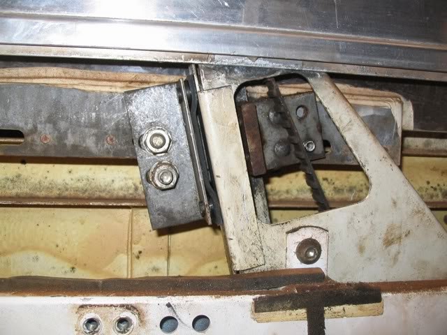
Figure 3 Solenoid and Plate Mounting - Top View |


Figure 4a and 4b, Solenoid and Plate Mounting - End View and Installed View |

(Rear Door, Locked Position, note the pusher rod will miss the plate when the handle is pressed)
Solenoid Operation
Solenoids have to be triggered via one or more of the following methods:
1 - a remote control, or
2 - an external, hidden, 2 way momentary action toggle switch or magnetic window switch, to lock or unlock all doors (simple, but a small security risk), or
3 - microswitch(es) mounted on the internal door frame/rails operated by tabs fitted to the internal door handle levers to unlock all doors when opened from inside (and relock all doors if 2 microswitches per door are used).
This is so you can go outside at night, for example, without the door locking behind you, and then relock all doors on re-entry. The remote is not necessary for this.
4 - Internal security switch to lock or unlock all doors from within the vehicle.
Any or all of these options can be implemented concurrently since all switches are wired in parallel. My recommendation for best functionality and reliability is to use all four methods.
Note: the remote and additional switch functions can be added after the system is otherwise operational.
Operating Summary
In this implementation, Power Door Solenoids can only enable opening or non-opening (locking) of doors while the handles remain in the locked position, by key.
Solenoids cannot lock the doors if the locks are unlocked by key.
Normal external and internal door opening and locking mechanisms are not affected by this mod, although the internal locking position could be deemed redundant (see below).
An internal, momentary action, security switch could be added (or by using the remote) to activate the solenoids whilst inside (at night for example) to enable, or prevent, access from outside. This does not affect operation of internal door mechanical door locks, but has essentially the same result, and is a bit easier than crawling around to each door in turn.
A remote control entry system can be used to energise the solenoids, subject to the above requirements and is the best solution.
Information on the Jaycar Power Door Lock system can be seen at http://www.jaycar.com.au/images_uploaded/powrlock.pdf
The Jaycar Door Lock Kit, part no. LR8812 at $39.95 for 4 door kit (cache)
Also Jaycar LR8839 remote keyfob entry system for $69.95 see http://www.jaycar.com.au/productView.asp?ID=LR8839&CATID=&keywords=
8839&SPECIAL=&form=KEYWORD&ProdCode
Only=&Keyword1=&Keyword2=&pageNumber=&priceMin=&priceMax=&SUBCATID= (cache)
Oatley have usable remote systems a bit cheaper and more flexible (but not as elegant and have to be assembled) see Oatley Electronics
The K203 is a 2 or 4 channel kit, with 2 channels used for Lock and Unlock functions.
The additional channels could be used for turning lights or other electrical equipment on remotely.
Dick Smith has a 4 door solenoid set for $50 and appears to be similar to the Jaycar kit. They are also available on-line via eBay.
Door Lock Mechanics
Construction of the door lock system needs a degree of precision fiddling to get the solenoids into the best position to operate the moving plate, while providing clearance from the door mechanism, door frame and window slide.
Four components must be manufactured for each door (see attached photos and diagrams, microswitch plates not shown). Note that the left and right hand doors will need mirror image brackets and plates.
1 - Right angle bracket, bolted on to the striker plate. This is attached by 2 screws to prevent movement and forms the basis for mounting a sliding striker plate extension. See picture below of solenoid assembled on rear door catch.
2 - Striker plate extension mounted on the above bracket by 1 screw and well greased lock nut, such that it can rotate. It has a 3mm hole to accommodate the actuating rod from the solenoid. (You'll probably need to remake a few of these before getting it right, since the shape depends a lot on the relative location of the door handle pusher, which can vary from door to door and with wear on the lock barrel).
3 - "Z" rail__ for mounting the solenoid, bolted to the catch mechanism frame, using
one existing and one new hole, both countersunk.
4 - Plate for mounting microswitches in the doors.
Figure 5 Mechanical Components for Door Locks |

I used 2mm steel for the brackets and moving plates since they have to bear all the force of the door handle pusher against the catch mechanism.
For the "Z" rail and microswitch plates I used 1mm steel (actually part of the Oka
outside skin, left over from access panels cutouts).
The microswitch plates were made from aluminium.
Countersunk screws are essential for fixing the major components, to minimise protrusions which could foul the door frame or the rotating door handle pusher, particularly the 2 shown below, which can prevent the catch fixings lining up with the door frame:
Figure 6 Solenoid in Position showing Screw Heads to be Ground Smooth |

Nyloc nuts are advisable to avoid loosening due to vibration (remembering this mechanism will difficult to get to for maintenance). Loctite could be used as well.
The manufactured components were painted with RustGuard for protection and to hide manufacturing deficiencies.
Figure 7 Moving plate showing ruler for scaling. |

Note, this is an enlarged moving plate from those shown in Figs 1 and 2. Subsequently, I had to grind off the corners (left and right as shown in red) so it didn’t foul the door frame and window slide in operation. The area where the pusher hits can just be seen (in blue) and shows why I had to enlarge it, it was very close to the edge.
Installation
Removing the Door Lock Mechanism
To remove the door mechanism:
1) Ensure the window is wound up, remove internal door handle and window winder,
2) Remove the interior door trim (the little plastic Christmas tree fixings can be difficult to remove. A sharp pair of pliers or scissors can be used to lever them out),
3) Loosen and move the window slide nearest the door catch out of the way (see below),
4) To move the window slide, remove the 2 fixings (6mm bolt to rail inside the door and 6mm screw at the bottom of the door),
5) Turn slide through 90º exposing its flat side before moving it (there is insufficient
space to manoeuvre it in its normal orientation),
6) Twist it up horizontal and rest it on the window ledge (see picture below, you will need to reposition it frequently to check clearances). Avoid damaging the window molding in the slide,
7) Undo the 2 screws holding the internal door handle mechanism in place,
8) Click up the external "U" shaped catch plate to the fully upright (door closed) position,
9) Undo the 4 Allen headed countersunk screws holding the door catch mechanism in place,
10) The door mechanism can now be manoeuvred out through the cut-out in the door.
11) To make it easier to work on the catch mechanism, remove the circlip holding the internal door operating lever on to door catch mechanism and remove the lever (replace the circlip to avoid losing it).

Figure 8a and 8b, Shows Window Slides relocated to enable catch mechanism to be removed |

The mechanism will probably be very dirty and covered with a thick layer of grease mixed with bulldust. It should be degreased before being worked on. (Note for reassembly: a foam surround to the catch mechanism would reduce ingress of dust).
While the door mechanism is out, the external door handle can be removed, although this is not necessary for this mod. Just check that the pusher lever is securely fixed to the lock barrel.
Also the window winders are worth checking at this time for operation of the friction pads, and tighten if necessary (see photos). Both our front windows slowly slid down on rough roads then rattled and let dust in. To improve the friction, I glued a section of rubber strip on to the pads before tightening.
Figure 9 Window Winder Friction Pads |
Rear Door Differences
The rear side doors are slightly different to the front cab doors.
They have no window slides but are narrower than the front doors and have restricted depth, so the "Z" rail bracket will need to be further modified to fit, but the principle remains the same.
Also the moving plate system for the cab doors didn't fit in the space available above the catch in the rear door, so a variation is required.
Instead of the plate moving down to enable opening, on the rear door it's hinged lower down so that it moves up to open. This only requires that the wiring to this solenoid be reversed, which works just fine since they are bidirectional anyway.
All door plates could be made this way if desired, but I had already done the cab doors before I discovered the rear door space problem.
Figure 10 Rear Door Solenoid Mounting |

(Note, the end hole is not required, it was left over from an earlier version which wouldn’t fit in the rear door.)
Fitting and Adjusting the Solenoids
Bolting the solenoids to their "Z" rails is easy enough if you can locate some 3mm x 35mm long screws and Nyloc nuts (Coventry Fasteners stock them).
Alternatively use 3mm or 1/8th inch tapped rod with lock nuts each end. Don't use the self tapping screws provided in the Jaycar kit, they could work loose through vibration or from the forces exerted by the solenoids.
The solenoids must point roughly in the direction of the hole in the moving plates, but it's not that critical. The 3mm holes in the moving plates are located so that they don't foul the rotating barrel lock pusher, and give the necessary movement of the plates when the solenoids operate (approx. 18mm stroke).
What is critical however, is that the solenoids and moving plates fit in the space available and don't foul the window slide or internal door lever when operating. Since each door catch pusher is slightly different in position and operating angle due to wear and assembly, even if only by a few mm, this can effect the operation of the moving plate.
Developing the solenoids fixings and moving plates for the door catch will therefore probably need several fit and adjust phases to ensure nothing fouls the door frame or window slide. I had to remake the moving plates a few times and grind edges off to ensure everything fitted.
Each door catch needs to be test fitted (including bolting the window slide back into place) and checked operationally before final installation.
I assembled and adjusted the microswitch plate as part of this test fitting, but then found it necessary to remove it so I could manoeuvre the catch mechanism and internal door lever through the opening in the door panel. I then refitted the microswitch plate when the mechanics were all OK.
Adjusting the length of the actuating rods can be time consuming and best done on the bench before the mechanism is fitted to the door. In fact the whole door system can be wired together and tested on the bench using the wiring harness provided before any fitting is started. All it requires is a 12 volt supply to the red and black wires, and the ends of the brown, black and white wires stripped so they can be touched together to simulate door switch operation.
Using the rods provided in the Jaycar kit, don't bend them yet, put them through the hole in the sliding plate, slide the brass tapped block provided on to the rod and secure with a 4mm bolt through the eye in the end of the solenoid arm.
This temporary arrangement allows the length of the rod to be adjusted on the bench before making the rod a permanent fixture. To do that, mark the exact hole centre of the solenoid arm on the rod and remove it so that a 90º bend (parallel to the plane of the moving plate to allow for movement of the striker plate) can be made in the rod at that point. Then reinsert the rod in the moving plate and poke the bent end through the eye of the solenoid arm. Hold in place with glue, tape, spire nut or other removable fixing.
The pressed steel flat nuts provided with the Jaycar kit can be used to hold the rods in place if opened out a bit and pushed on the rod. Tap a piece of rod through them first to open them out, slide them on to the rod when in position and then pinch the little tabs flat, if necessary, with long nose pliers. They hold quite tight but a dob of glue would make quite sure, but still be removable.
When in place, the rod should be tight, but loose, if you see what I mean. Tight enough so there is minimal slop as the solenoid operates, but loose enough to allow for movement of the striker plate without placing stress on the solenoid arm when the door handle is pressed. Some experimental rod bending might be needed to achieve this outcome.
As insurance against a solenoid or electrical failure causing a door to be stuck in the unlocked position (ie. can still be opened but not locked), a hole could be drilled in the side of the door frame above where the catch mechanism is bolted and in line with the moving plate.
This would enable a screwdriver or similar to be inserted to lever a stuck plate into the lock position and the key then used to unlock and relock the door. The hole should be plugged by a blanking grommet. If it is a hard fault, the system should be switched off (remove the fuse) and the key used until the fault is fixed.
Door Lock Electrics
The wiring harness included with the Jaycar kit is comprehensive and long.
However, it assumes that the control box is installed first and the cables are then run out to each of the door solenoids though the body and into the doors. In practice, I found this to be back to front and impractical.
Since every car and installation will be different, it's more logical to decide on the location of the control box, fit the door units, then connect the wiring loom to the solenoids, feeding the loom through the internal space of the door, across the hinge area and working back to the control box in the body of the vehicle.
You can't do that with the harness as provided, so the wires to the doors will need to be cut near the control box connector and rejoined after feeding them from the doors and getting the lengths right.
The location for the control box needs to be near a source of +12 volts (fused, but unswitched so it's on all the time), ground (0 volts), and any internal switches. Under the dashboard to the right of the steering wheel is convenient in our Oka, and an internal lock/unlock security switch can be located nearby. If a remote control is ultimately added, its control box can be located here too.
BTW, note that the Jaycar documentation refers to +12 volts and -12 volts. They really mean 0 volts or ground in place of -12 volts.
Figure 11 Control Box mounted behind Dashboard |

For provision of an external switch, 3 wires (brown/white/black) can be added from the internal switch and taken to the centre console area for access to the outside of the Oka in your chosen location. The lengths of the wires are not critical and can be very long if desired so it could be fitted almost anywhere.
Feeding the wires across the bottom of the Oka doors is fairly easy, but must be low enough to avoid the window when wound down. A new 12mm hole (with a grommet) will be needed on the hinge side of the door and a corresponding hole (with a grommet) on the fixed door frame, in a position which enables the wires to make their way into the cab. This should be a few cms higher or lower than on the door to allow the cable to twist and flex as the door is opened. Where the wires run outside the body of the Oka, cover them with some plastic sleeving or spiral wrap to protect them.
The drivers door cable has 5 wires in it for the master solenoid, the other door cables comprise only 2 wires for the slave solenoids. An additional 3 wires are required to doors fitted with microswitches (except the drivers door, see below). Extra wires and the microswitches, if fitted, are not part of the Jaycar kit.
When laying out wiring, allow for additional white (Lock), brown (Unlock) and black wires to the passenger and rear door(s) for microswitch installations (see diagram below). No additional wires are required for the drivers door since the white, brown and black leads go to the master solenoid anyway. The drivers door microswitches can be connected into these existing wires.
All like coloured wires will ultimately be connected together but it's not necessary to bring them all to the control box first. Wires from the rear door can be connected to the passenger door wires in the passengers dashboard area and one set taken across to the control box.

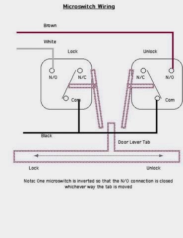
Figure 12a and 12b, Electrical Block Diagram and Microswitch Wiring Diagrams |
Microswitch Implementation
I fitted each door with 2 microswitches, one to unlock the system when any internal door handle is used to open a door, and one to sense that any door has been mechanically locked from inside and relock all doors. This second switch is only really necessary on the rear door, where you might want to relock all doors after reentry at night, but while I was working on them anyway, it was easy enough to put 2 in on all doors rather than have a change of mind later.
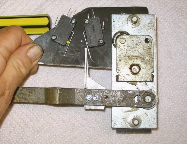
A tab was bolted to the door operating lever in the opening of the inside door panel. This pushes the actuators on the 2 microswitches as the door lever moves. See pics below (of the rear door system).
Figure 13 Microswitch Panel in Normal Position |

The microswitches were mounted on the inside of an aluminium panel bolted to the door panel. On the rear door, the door handle fixing bolts can be used to hold it.
The location of the switches requires a bit of trial and error to ensure they operate at the right time but don't get too stressed by the movement of the tab. I made the tab from a piece of plastic angle to give some flexibility when striking the microswitch actuators. Also I angled the microswitches so that there was more of a wiping action. Both of these techniques will reduce the stress on the switches. The positioning of the switch plate needs to ensure that the tab won't slip past the switch actuators at the normal extremes of movement and bending of the door operating lever. That's why the switches are on the inside of the panel.
Figure 14 Microswitch Panel in Unlock/Open Position, which is spring loaded
Electrically, all like switches are connected in parallel. Even if one switch is in the lock position, operating any of the other unlock switches still triggers the system, since the control box senses the negative edge of a switch signal, not it's on or off status. |

Remote Control
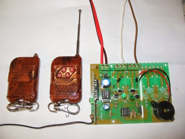
A remote control can be added to the system quite easily. I used a kit from Oatley Electronics (K203 plus K203E) receiver and two Tx7 key fob transmitters.
The receiver kit provides 4 channels (by adding the K203E components), 2 of which I used for Lock and Unlock. The other 2 will be used for Internal Lights on/off, and External Lights on/off. Alternatively, these 2 extra channels could be used for any other remote electrical switching (eg TV/Radio or Car Alarm).
The key fob has 4 buttons plus a sliding cover to protect them from accidental use. It also has a small telescopic antenna which Oatley claim increases its range to 100m plus, but is not needed for short range.
I could have used the add-on remote kit from Jaycar (LR8839) which comes already assembled and is easier to incorporate. However it only provides lock and unlock functions and I wanted a bit more flexibility.
The Oatley key fob transmitter is easy to assemble, just put the battery in and screw together.
Figure 16 Key Fob Transmitters and Receiver Board |
The receiver is an electronics kit which requires assembly of a printed circuit board and is a bit more complex. I left out several components which are unnecessary for triggering the door lock system but which would be required for powering other electrical equipments. I can provide additional info on the receiver assembly if needed.
The circuit board will require mounting inside the vehicle near to the control box. It requires +12v and ground, and 2 outputs (I used “A" for Lock and “B" for Unlock) must be connected to the White and Brown control box wires. I mounted it under the centre dashboard area. The 6 inch antenna wire can just dangle somewhere.
I fitted a small piezo buzzer to the “Lock" output so it beeps when the “A" button is pressed to indicate the doors are being locked. I figured unlocking the doors was pretty self-evident anyway, but it could be connected to the unlock function too via a couple of diodes. The receiver could also be used for flashing the lights or beeping the horn to indicate that it has done its job. This would require the additional components (relays mostly) that I left out of the receiver construction.
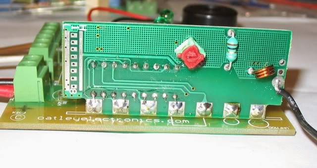
Figure 17 Receiver Circuit Board. |

The area under the buzzer is where the additional 2 channel components will fit when I get around to them.
Note 1: The key fob transmitter and receiver can be encoded to provide security so they will not respond to other systems encoded differently. You can choose from thousands of codes, implemented via wire links. Sketchy details are in the kit or on the Oatley website. The system will also operate perfectly well unencoded but with less security. See encoding areas in the photos below. The receiver and both key fobs must be encoded exactly the same and this will require a fine soldering iron, thin wire and a steady hand.

Figure 18a and 18b, Encoding Connection Areas on receiver and Transmitter circuits. |
Both must be wired the same.
Note 2: the K203 receiver kit is based on a small PIC microprocessor which decodes the transmitter signals and provides a timed momentary or latched output signals. It therefore has the potential to be reprogrammed to perform other functions (such as a longer timer or flasher or personal alarm) using a PIC programmer.
Potential Problems and Fixes
Shock and Vibration
Since the solenoids are not energised all the time, only when moving the plate up or down, I was concerned initially that vibration from the moving vehicle could rattle the moving plates down from their locked to unlocked position. However, that is the fail-safe position anyway, normally one wouldn't travel with doors locked. When the moving plates are up in their locked position, the vehicle will generally not be moving so this problem won't arise.
Contrary to this however, in practice, the action of the pusher on the moving plate initially caused the plate to work upwards to the lock position, after 30-40 presses due to the leaning action of the catch plate when pushed, and the proximity of the pusher to the edge of the moving plate. This is not a fatal flaw, just a bit annoying.
This was fixed by remaking the plates slightly larger so the pusher was further away from the edge of the plate, tightening the lock nut further and then putting on a separate nut locked up tight against the lock nut to keep it tight. Even Nyloc nuts can work loose it seems when used to lock a rotating screw.
With the rear door mechanism being reversed there is an outside chance of the moving plate working down to the locked position while on the move, but it is only the rear door, and the mechanical door mechanism will still work anyway.
Experimenting with tightening the bolts holding the moving plates suggests that they can be bolted up quite tight, if well greased, so they can rotate but not drop down, and the solenoids are still powerful enough to operate them.
Getting Locked Out
After fitting this mod, it's still technically possible to lock yourself out of the Oka, but you'd need to plan ahead. You would have to lock the doors electrically, leave or put all the keys and remotes in the vehicle, get out and shut all the doors, This will lock you out, since the door locks are always keyed in their locked position for the system to work.
That's why you need a hidden, external lock/unlock switch, which should be tested regularly so it will work if and when needed. This switch should be a marine grade, 2 way momentary action switch to survive the elements and can be wired in parallel with the microswitch connections, since it does the same job. It needs to be momentary action in both directions so it does not interfere with normal microswitch operation. Dick Smith P7658 and P7689 (very small) switches would work but both need protection, maybe mounted in a small plastic box. At a more professional level, Carling Technologies manufacture an array of marine switches, available from Amelec Australia in Perth, www.amelec.com.au.
Note 1: if the switch ever fails, just whip the white or brown connections off the back (one of them will unlock depending on how it's wired) and short to the black wire or to the chassis, or just short the terminals of the switch with a piece of metal. (You can't use a key since you locked them inside).
The switch should be mounted in a hidden but protected area so that access is possible to the rear wiring. An alternative (or addition) would be a miniature reed switch mounted inside the windscreen or window. This can be activated through the glass from outside by a small magnet carried on the key ring or stored outside the Oka somewhere, and would avoid the need for an external switch. Keep the magnet away from wallets or purses however, or it might zap your credit cards.
Note 2: it has always been possible to lock yourself out of an Oka even without this system installed. You would have to lock all the doors with the key while they are open, put all the keys inside the vehicle and then shut all the doors. So all this implementation does is to give you an alternative method of locking yourself out!
Stuck Plates
In the event of a stuck plate or solenoid/electrical failure, the door trim would have to be removed so that the offending plate can be manually shifted to the unlock position. The system should also be disabled (removing the fuse is the easiest way) until the problem can be rectified. Normal operation using the key is then possible.
If felt necessary, a hole could be drilled in end of the door frame so that a screwdriver could be inserted to shift a stuck plate. The door trim would then not have to be removed.
Other photos or info on the implementation are available to anyone who wants to do
this mod. Contact me at dandjribbans at internode dot on dot net
