


These are very handy for raising the vehicle but are not perfect, so I have added some additional jacking point cut outs on the sides of the bullbars. They can be added even if you don't have the standard jacking points. Bolt-on jacking points are also available from 4WD shops but these are intended for front or rear bull bars, or chassis fitting, and would protrude if fitted to the side of the vehicle, and make it more difficult to attach a jack.
[Caution: Although I only ever intended to use these new cut outs to provide added stability and safety when using screw or hydraulic jacks, they are actually strong enough to raise wheels off the ground. They should never be used as the sole means of doing this however as you would be relying entirely on the integrity of the bolts holding the bullbar to the chassis. They should always be used in conjunction with other support devices].
Problems with the existing system
1) the vertical frame next to the LHS jacking point on the front bullbar fouls the hi-lift jack mechanism making it difficult to fit the jack securely,
 |
| The jack fouls this upright. |
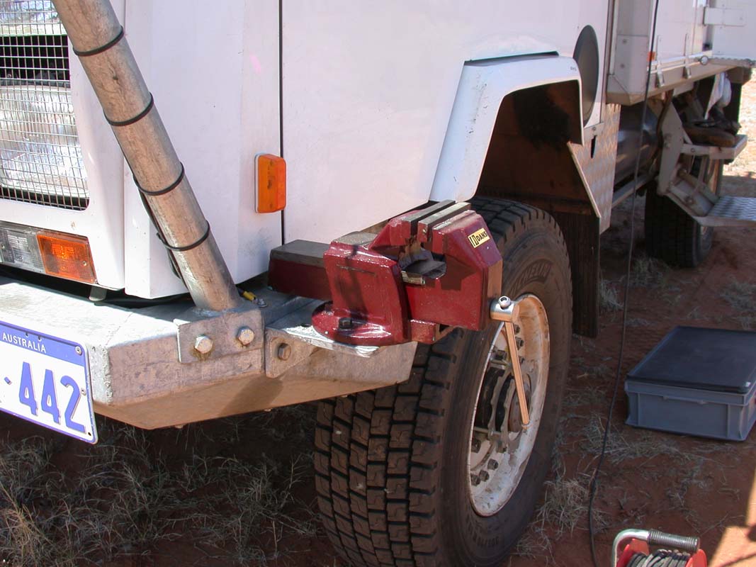
2) at the back, anything fitted to the rear of the vehicle, like wheel mounting frames and gates, have to be moved aside or opened to get at the jacking points. In our case the rear number plate also covers one jacking point and gets bent in half every time we have to use the jack,
 |
| The rear jacking points are hidden and difficult to access. |
and, most importantly,
4) the jacking points are about 1/4 of the way across the vehicle so when you want to lift one corner, you are actually lifting a lot of the opposite corner as well. This makes lifting more difficult and places additional stress on the jack.
The Solution
The Solution
A simple solution is to cut rectangular holes in the side of the bullbars, as shown in the photos below, to fit the jack in from the side. The holes can be easily cut using a small grinding wheel and I drilled the corners of the holes first to give them more strength. The dimensions for mine were 60 mm x 40 mm (about the same size as the Oka jacking points), but this will depend on the dimensions of the lifting nose on your jack. I didn't make the cut outs big enough for the whole jack nose to enter as that would have weakened the structure. It's sufficient for the nose of the jack to fit in up to its strengthening brace, as is does in the original jacking points.

 |
| ...and on the front bullbar next to the step. |
 |
| Welded reinforcing bars on the inside of the rear bullbars. |

Results
I found these new cutouts to be surprisingly effective and it's a great help to be able to open the rear hatch (which is where my tools are kept) while the vehicle is raised. Previously, I had to get everything out that I might need for the job before raising the vehicle and inevitably I forgot something critical.
I found these new cutouts to be surprisingly effective and it's a great help to be able to open the rear hatch (which is where my tools are kept) while the vehicle is raised. Previously, I had to get everything out that I might need for the job before raising the vehicle and inevitably I forgot something critical.
With the original jacking points, it took a lot of effort to raise one wheel off the ground, in fact you can see the bar of the jack deflecting under the strain, even though it is still well within its strength limit. With the new side fixings that task becomes a lot easier and safer (mathematically, about 25-30% less effort required, but slightly more lifting height needed on the jack).
[Note: due to their height, Oka's need an extended length 60 inch (152 cm) high lift jack to be effective, such as ARB 204 or 304 see here, about $200. BTW the capacity quoted by ARB is wrong. It's not 1050 kg, it's 2113 kg according to the US manufactures web site here, and they are tested to 3175 kg.
I've raised that inconsistency with ARB and they say it's due to the requirements of the recently modified Australian Standard for jacks in which the capacity of the jack must now be defined by the capability of the handle, not the lifting capacity of the jack.
This doesn't make sense to me since it infers that the handle is only half as strong as it needs to be to use the lifting capacity. The Instruction Manual for the Hi-Lift jack on their US website states that the jack "Meets applicable requirements of ASME/ANSI B30.1 2004 AU/NZS 2693:2007". It's available here.
As a result of my correspondence with ARB, they are now amending their web sites to remove inconsistencies and downgrade their capability to reflect the new requirements. They even offered me my money back (after 4 years!) if I wasn't happy with the new interpretation.]
Side fixings might also make de-bogging a wheel easier (as it did when we got bogged on the Hunt Oil Road, in WA), since you don't need any access under the vehicle. We carry a hub adaptor as well, which allows the hi-lift jack (or a tall screw/hydraulic jack) to be used directly on the wheel hubs for this purpose, but the hub might also be buried so bullbar side fixings might be more useable.
Caution
Caution
As with any jacking method however, never rely on just one jack. Leave the wheels on whenever possible, use axle stands in addition to the jack, and chock any unlifted wheels. A spare wheel jammed under the differential can provide additional security.
While you are implementing this mod, it might be wise to check the bull bar bolts for tightness and strength grade. They need to be a fairly high tensile strength. I know, we broke one on the Anne Beadell Highway and bull bars are not the easiest of things to remove and replace.
No comments:
Post a Comment