Welcome to David and Janet Ribbans blog

We live in Adelaide, South Australia and enjoy travel in the Australian outback in our Oka 4WD motorhome, hence the blog title.


To quickly locate any of our more than 80 travel and technical articles, use the drop down menus below or scroll down the lists in the right hand sidebar. But please read the disclaimer first, we've tried to be accurate and current but things can change...
You can also visit the official Oka 4WD website here.

Pandora Web Archive


We're now honoured to have our blogs archived
on the National Library of Australia's Pandora Web Archive.
Bookmark this link to the archived version in case anything ever goes wrong with Google, or I accidentally hit "Delete All" in a fit of pique. The drop down menus above might not work in the archived version but everything else should...
Showing posts with label Problems. Show all posts

Thursday, 12 December 2013

Another broken spring bolt...

Our Oka has been left idle for the past couple of months since returning from our recent trek across the WA deserts.

But yesterday I removed one of the gas bottles for use at a Christmas BBQ and something around the rear spring looked a bit odd...

IMG_3536-2013-12-12-08-29.JPG-2013-12-12-18-59-2013-12-12-18-59.jpg

The rear suspension pin protrudes 50mm, which it shouldn’t

The spring bolt behind the gas bottle is protruding about 50mm whereas it should be flush with the chassis spring mount. The Nyloc nut on the inside of the bolt is still in place so it’s not rocket science to surmise that the bolt is broken in the middle, probably across the grease hole which would be its weakest point.

Gouges on the side of the gas bottle suggests that the broken bolt was being held in place by the bottle, which is probably better than the bolt falling completely out, but it may have been this way, unnoticed, for quite some time which is a bit of a worry.

The really strange thing about this event is not that a spring bolt has broken, we’ve experienced a few of those before, but that all spring and tyre related problems have always been on the same wheel, the drivers side rear. That now makes 3 spring bolts, 2 broken springs, a bogging and a tyre staking all on the same corner. What are the chances of that happening? I don’t believe there is anything very different about this corner, the construction and loading is very similar to the opposite side.

Replacing the bolt is not a major task, I have spares, it’s just a heavy job. The real questions are why and how to prevent future occurrences?

All other spring bolts apart from the 2 rears have been upgraded to 20mm diameter suspensions pins which are a lot stronger than the original 16mm bolts. These 2 rear bolts had previously been replaced by ultra-strong crankshaft quality 16mm bolts, running in bespoke replaceable bushes, and were claimed to be unbreakable, until now.

IMG_0917-2013-12-13-08-29.JPG-2013-12-12-18-59-2013-12-12-18-59.jpg

Replaceable screw in bushes for the previous 16mm rear suspension bolt upgrade

So I shall now upgrade the remaining 2 bolts to 20mm pins, which is not so easy (and the reason why they haven’t been done previously) since the chassis mounts were specifically designed for the replaceable bushes and I’ll have to redesign and reweld them to take 20mm pins. I was going to check and replace the urethane bushes anyway before our next trip.

I might consider going up market further to the 25mm suspension pins as fitted to the new NT model, (actually the NT pins are 1 inch or 25.4mm diameter). However more thought would be required since the spring eyes are not much more than 25mm anyway, actually around 32mm, which means the wall thickness of the urethane bushes can only be between 3-4mm (the NT pins actually run in steel/phosphor bronze bushes which are only 3mm thick).

The bolt replacement task is not a huge one and made all the better by the fault being discovered at home rather than on the side of some remote, hot, dusty, insect ridden track like previous similar events.

Here I have the time, facilities, shelter and materials access to do it at my leisure, all I need is the motivation but they don’t sell that at Bunnings, I know, I asked once which aisle it was in.

Since starting this article, I’ve replaced the rear suspension pins with high tensile 20mm bolts and fitted bushes to provide a larger surface area for their support.

IMG_4935-2013-12-12-18-59.JPG-2013-12-12-18-59.jpg

To do that I had to drill out the holes in both side plates to 25mm to accept the bushes, which would have been much easier if I had been able to turn the chassis on its side and use my large pedestal drill.

As it was I had to buy a new larger power drill and go up in size progressively from 20 to 25mm.

The bushes were fashioned from former Oka suspension bushes, cut to size and drilled out to 20mm to fit the new bolts. I also fitted new urethane bushes although the older softer versions weren’t as worn as I had expected.

IMG_4912-2013-12-12-18-59.JPG-2013-12-12-18-59.jpg

This is a simulation of the set up with bushes and thrust washers, and steel samples providing the side plates

(The previous broken bolt shown for size comparison)

IMG_4913-2013-12-12-18-59.JPG-2013-12-12-18-59.jpg

The former Oka bushes (R) were 1 inch external diameter but, allowing for some wear, reduced to 25mm quite well to fit the new holes, and when drilled out to 20mm leave adequate sidewall thickness

Because I could only get long enough Class 12.9 bolts in socket head versions I fitted a retaining and anti-rotation wire to their heads.

Drilling HT steel is not easy and the 3mm drill bit crackled as it went though. Smaller drill sizes just snapped. For good measure I also drilled the threaded end to accept an R pin so the nyloc nut can’t ever come off.

IMG_4942-2013-12-12-18-59.JPG-2013-12-12-18-59.jpg

While I had the opportunity, I changed from the lower to upper bolt hole position. This lowers the suspension by around 30mm and allows the airbags to take more of the load levelling task. It also tilts the differential yoke upwards slightly taking some stresses off the UJ.

All 12 suspension bolts/pins on our Oka are now 20mm HT steel so we should have no more failures of this kind.

Tuesday, 3 December 2013

Thursday, 1 August 2013

Debogging our Oka

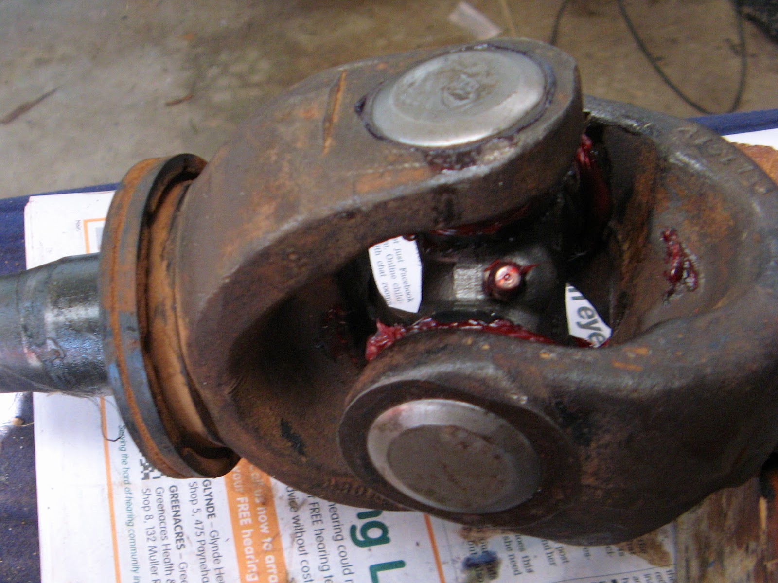
The afternoon of 26 July didn’t go quite according to plan.

For a start it became cloudy, thus ruining our run of cloudless days, and then, close to Alexandra Spring on the Hunt Oil Road we met a diversion off the main track, which we learned later was to avoid a dangerous wash-away. That diversion took us across a suspicious looking swampy area where a previous vehicle had become bogged. I took a look around and judged I could pass by that soft area a meter or so to the left.

Unfortunately I was wrong.

Through poor judgement and bad fortune (for who would expect a swamp in a desert?), my chosen route was also very soft and we slid sideways into the same trench that the previous vehicle had ended up in.

Bugga, and thrice bugga.

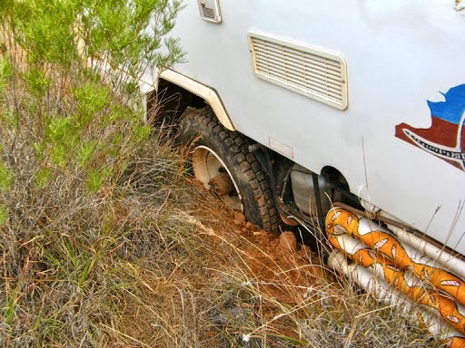
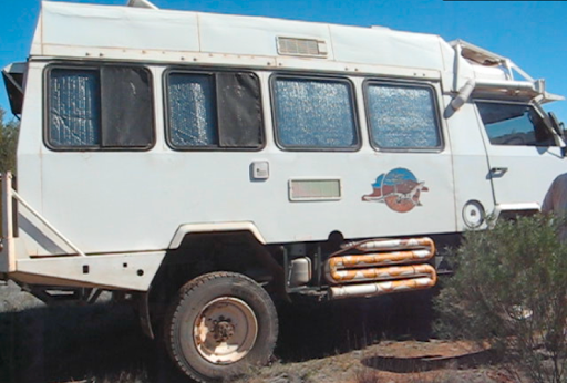
Our crashcam video camera recorded the “Oh Sh*t” moment for posterity. Not only did we fail to proceed forwards but we also failed to retreat backwards as well, both drivers side wheels were bogged down to the axles with the other wheels spinning on the soft surface. In fact the diff’s were on the ground and we were leaning at more than 15ยบ.

The problem we worked out later was that the water from the spring seeped under the soil making it wet from underneath while it looked firm and dry on the surface. The next 50m of track looked very much the same.

IMG_1742-2013-07-29-21-23.JPG-2013-07-31-15-03.jpg

IMG_1743-2013-07-29-21-23.JPG-2013-07-31-15-03.jpg

We might have been stuck be we still had good HF radio communications!

IMG_1754-2013-07-29-21-23.JPG-2013-07-31-15-03.jpg

It was getting late in the afternoon so we made an attempt to stabilise the Oka with the Hi Lift jack so it didn’t slip any further over night. That was difficult since the jack kept sinking into the soft surface but eventually with some large rocks we got some purchase and then retired for a strange slope-y dinner and sleeping arrangements. Hammocks would have been useful.

IMG_1752-2013-07-29-21-23.JPG-2013-07-31-15-03.jpg

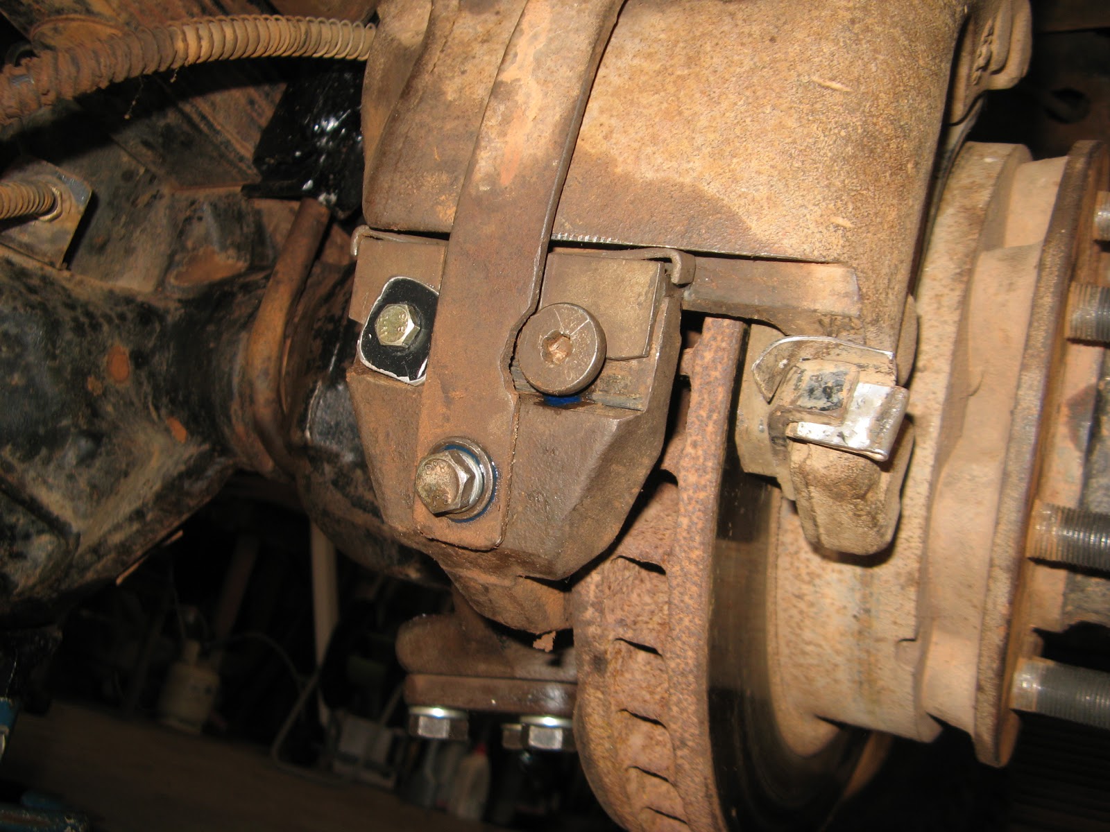
Front diff on the ground.

IMG_1748-2013-07-29-21-23.JPG-2013-07-31-15-03.jpg

Rear diff very nearly on the ground.

IMG_1747-2013-07-29-21-23.JPG-2013-07-31-15-03.jpg

27 July

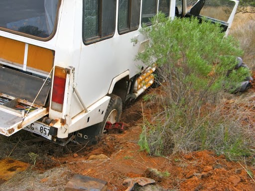
We had a slightly sleepless night, partly due to the angle of the bed and partly due to apprehension over how we were going to extricate ourselves from a difficult bogging situation, all by ourselves and a long way from help. Our bogging site was in almost the dead centre of the Gibson Desert in WA and we had seen no one for 2 days.

Considering our predicament we don’t look too concerned do we? Well that’s because things could have been worse.

  • We had made contact with our HF radio so we weren't totally cut off.
  • We had food and water for a couple of weeks so provisions weren’t a problem.
  • We weren't injured and there was no immediate threats or danger,
  • We plenty of spares and equipment and we’re fairly experienced with outback travel.

Almost the perfect bogging environment you might think.

IMG_1750-2013-07-29-21-23.JPG-2013-07-31-15-03.jpg

We were up early for obvious reasons having mentally been through the all the options and plans we had available to us.

It was very cool and cloudy that morning which was good for the hard labour that was before us, in fact we even had a shower of rain.

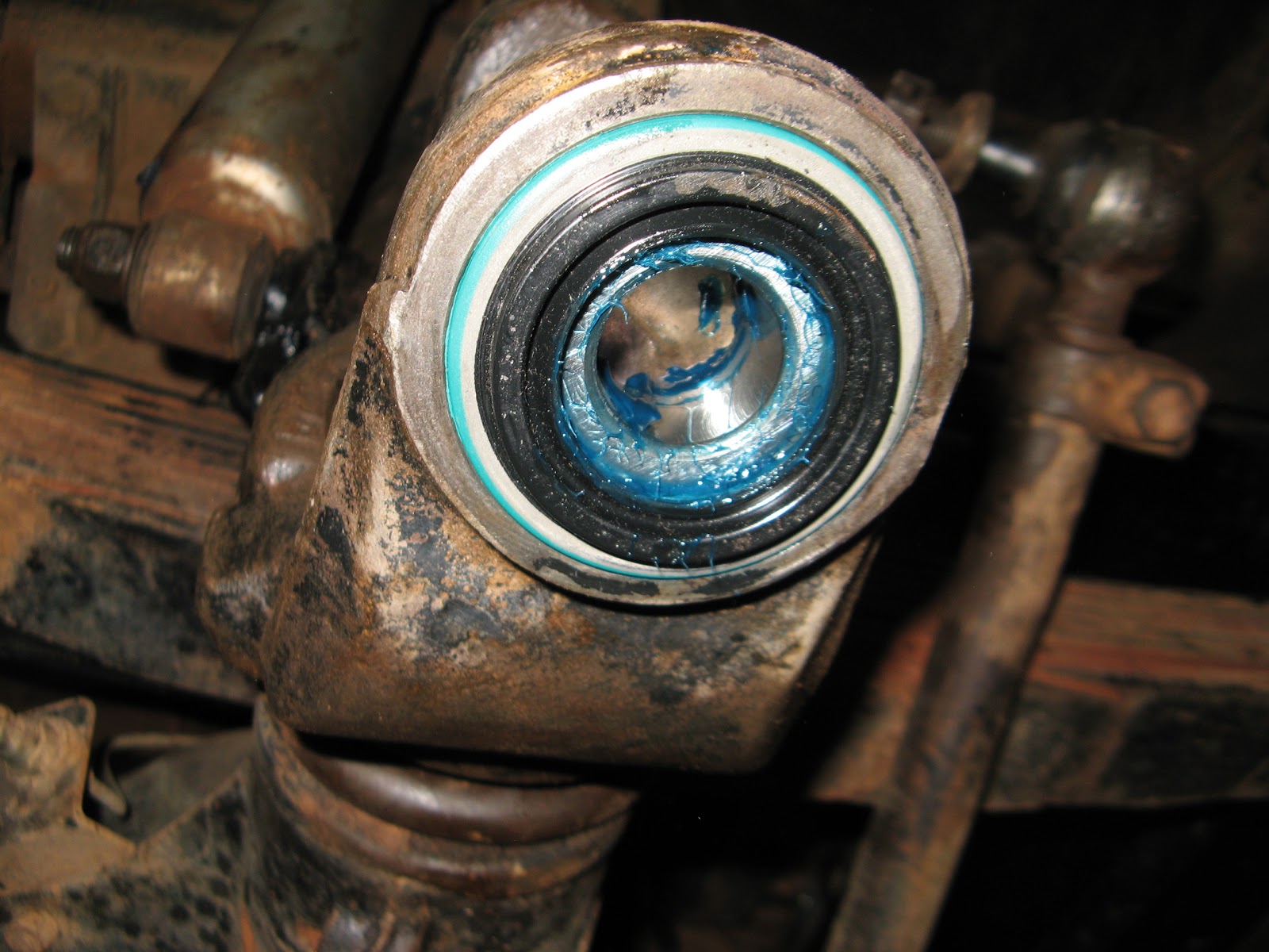
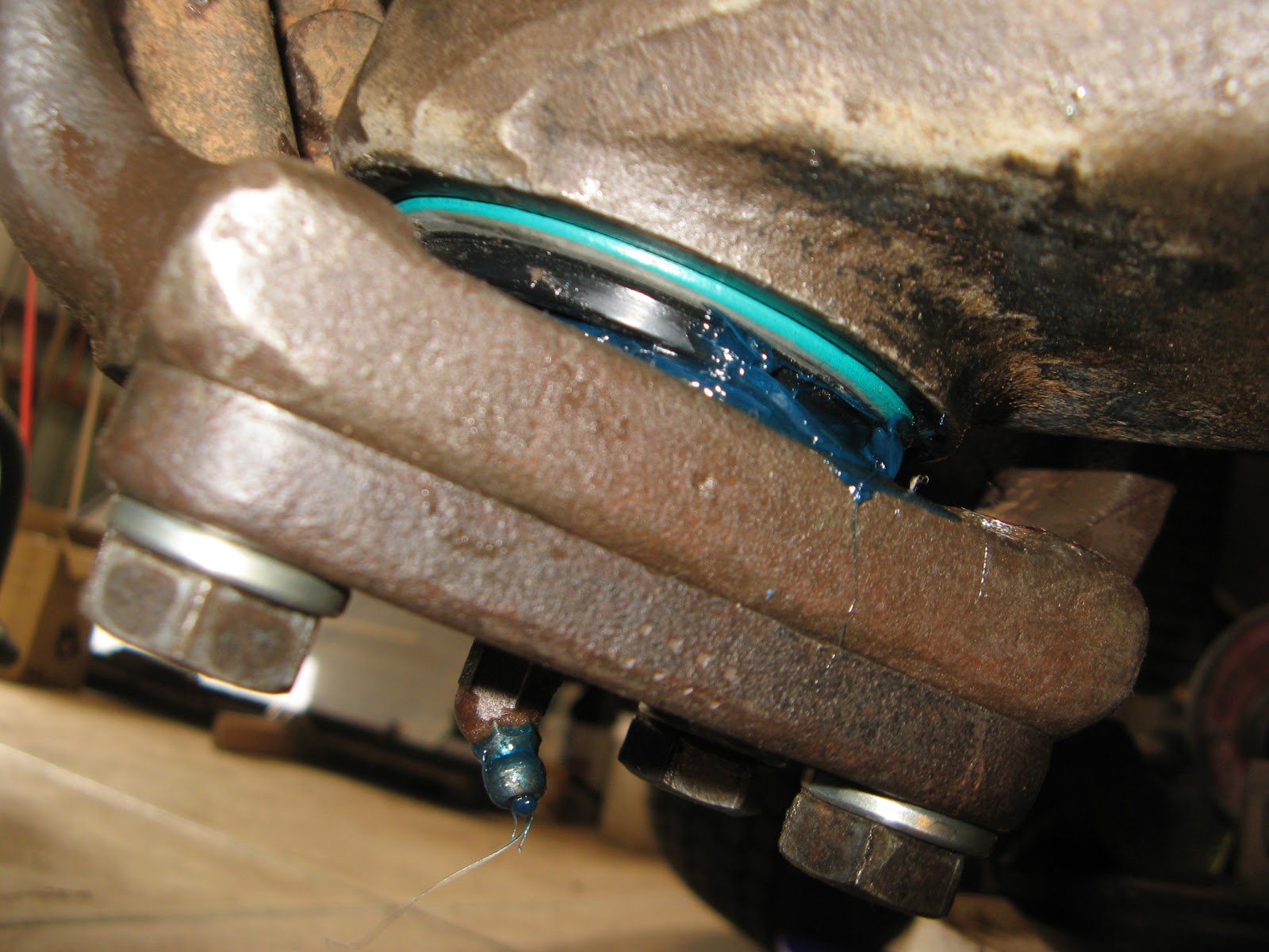
The first thing we had to do was dig out the wheels to see the extent of the problem. That meant shifting grass, shrubs and soft sandy soil to access the wheels.

IMG_1755-2013-07-29-21-23.JPG-2013-07-31-15-03.jpg

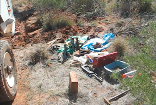
Next we had to establish a base camp, take out all the tools and equipment we would need, and lighten the Oka as much as possible by removing the spare wheels and heavy tools, and transfering the fuel from the rear to the left side tank. I always use fuel from the left side tank first for this very reason.

IMG_1756-2013-07-29-21-23.JPG-2013-07-31-15-03.jpg

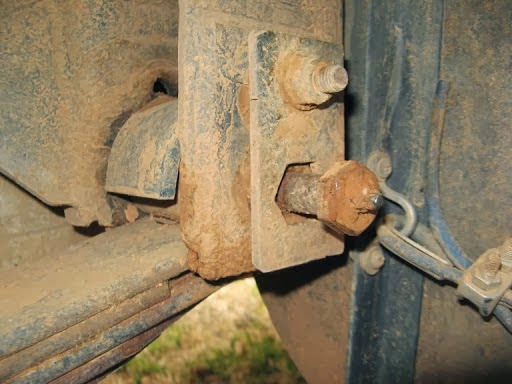
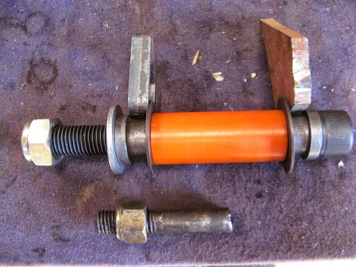
The hi lift jack was also causing a problem in that it would raise up but not lower without difficulty so next I had to fix that. I’d overhauled the jack last year with replacement pins and springs but failed to notice some wear on some sloping edges which was preventing the release pins from sliding smoothly. I filed them smooth, reassembled the jack and greased the slides and that was all fixed.

IMG_1757-2013-07-29-21-23.JPG-2013-07-31-15-03.jpg

Before and after shots, all good now.

IMG_1763-1765-2013-07-29-21-23-2013-07-31-15-03.jpg

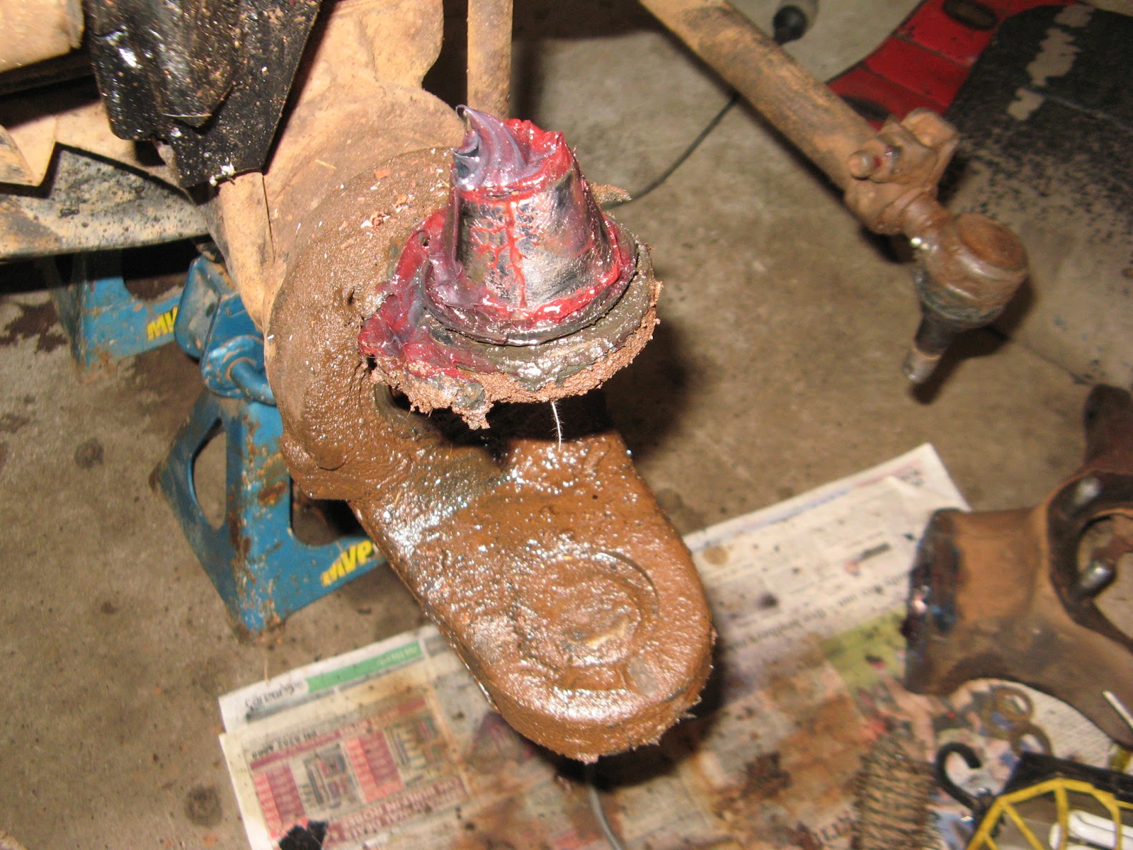
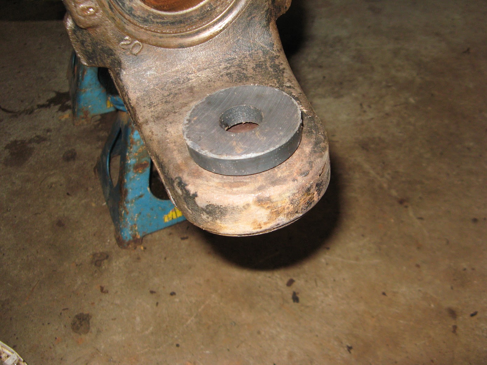
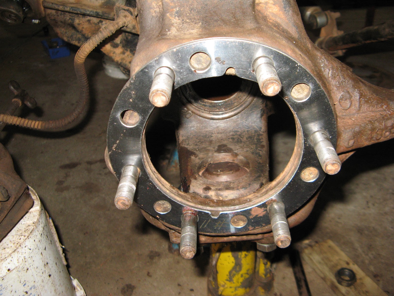
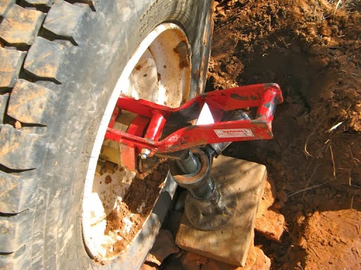
But the hub adaptor, which was supposed to enable us to lift a wheel directly using the hi lift jack, failed miserably and buckled under the weight of the Oka, so we had to use a different strategy.

IMG_1759-2013-07-29-21-23.JPG-2013-07-31-15-03.jpg

We alternately raised the rear of the oka with the hi lift jack and raised the wheel hub using a large screw jack on the unbuckled section of the adaptor. Using this process we eventually raised the wheel sufficiently to fill the void underneath. We also had to do the same with the front wheel.

The biggest problem we had was stabilising the jacks which kept sinking into the mud. Eventually enough large rocks underneath provided a firm base to raise the Oka.

We had to dig out a ton of soft moist soil to get access to the wheels and carry what seemed like a ton of rocks in shopping bags 50m from a nearby creek bed to create a road way under the bogged wheels. We also had to fill the area between the wheels to carry the front wheel backwards without it sinking in again.

But the Oka was eventually raised on to it’s new roadway sufficient for extraction. It took us round 8 hours of hard work, and we were physically knackered. It leans the other way now while on it’s jacks, which is good.

IMG_1767-2013-07-29-21-23.JPG-2013-07-31-15-03.jpg

Once the jacks were removed it came down almost level, ready to drive out.

Screenshot2013-07-28at5.45.16PM-2013-07-29-21-23-2013-07-31-15-03.png

After tentatively backing off our home made pavement, the Oka was finally out of the bog and on firm ground again, nearly 24 hours after we got stuck. A long hard slog but we’d done it. Even the sun came out again.

Screenshot2013-07-28at5.47.50PM-2013-07-29-21-23-2013-07-31-15-03.png

Janet showing off her newly built roadway.

Screenshot2013-07-28at5.50.13PM-2013-07-29-21-23-2013-07-31-15-03.png

Screenshot2013-07-28at5.50.39PM-2013-07-29-21-23-2013-07-31-15-03.png

The front wheel did miss part of the the new roadway on the way back but that was only a quick job to construct anyway.

Screenshot2013-07-28at5.51.53PM-2013-07-29-21-23-2013-07-31-15-03.png

Once out and after lunch (we suddenly realised we’d had nothing to eat all day), we now had to reinstall all this stuff.

Screenshot2013-07-28at5.56.07PM-2013-07-29-21-23-2013-07-31-15-03.png

Screenshot2013-07-28at5.55.25PM-2013-07-29-21-23-2013-07-31-15-03.png

It was about this time that we heard the sound of an engine. Just our luck for someone to come along a couple of hours after we needed some help.

A few minutes later 3, 4WD’s appear from in front of us. We waved them down to prevent them suffering the same fate as we had and they walked over to see what our problem was.

They couldn’t understand how they got to be on the same diversion track as we were on, and reversed out to survey the area. We maintained CB radio comms while they scouted around and located the main track about 100 m away from us to our left. It had a dangerous wash-away on it, which was the reason for our diversion.

They carefully passed by the wash-away and came back up behind us this time, to render assistance and help us reload the spare wheels and heavy tools. They also surveyed a cross country route from where we were on firm ground to the main track beyond the wash-away and insisted on staying until we finished packing up and then guided us across the swampy and rocky ground to the main track. Then we were all OK and on our way again.

Since we didn’t know the extent of the soft ground beyond us, without their help we would probably have turned around and backtracked 200km to find a more reliable track. Now we had their knowledge of the track ahead, we were able to carry on and complete the track as planned to the Gunbarrel Highway.

The 4wd’s were from Bendigo and were the only vehicles we saw on that track in 4 days. They had turned my poor judgement and bad luck into a successful trek. Just another outback adventure.

Looking back, we had successfully located the only soft section of track in 250km, but it was almost our undoing. We were quite elated to have been able to extricate ourselves from probably the most serious situation an outback traveller could get into, and we had done it alone and with only the equipment and skills we carried with us. Experience and self-sufficiency planning had made the difference, but we also had our HF radio, and if necessary an EPIRB, had it been a worse situation.

What else could we have done and what have we learned?

While the Bendigo team was with us, we discussed the pros and cons of diff lockers and I made a throw away remark that if we’d had diff locks, we wouldn’t be holding this conversation. However, if we did have diff locks they would not have stopped us getting bogged in the first place, that was caused by a combination of an error of judgement and bad luck (a swamp in the middle of a desert?), not inadequate equipment.

And when bogged, most of the weight of the Oka was on the bogged wheels with much less weight on the other side wheels so they both spun. Even if they had been locked, the bogged wheels would have turned but would not have had the traction to crawl out of the depth of wet soil they were in. So while diff locks might have advantages in some situations, I don’t think they would have helped much in ours.

Also if we’d had a winch, it would not have helped since there were no sturdy enough trees within 100m to attach a winch cable to. We could have buried a spare wheel as an anchor but as far as I know that has only ever been a theoretical idea to try, not a proven solution to the lack of trees, vehicles or other solid objects.

Bigger sand mats might have helped but first we had to fill the void to raise the wheels to near ground level again. The rotating wheels just spat out anything we wedged under them since there was insufficient weight on them. We tried small sand mats, expanded aluminium, branches and rocks. All were spat out.

So the remaining option is to travel with other vehicles for mutual support but that is not always possible or practical.

We also learned that 2 powerful jacks with high lift are essential. Neither of our jacks alone would have enabled us to raise the rear wheel high enough to pack rocks underneath it. The hi lift jack is operating at it’s extremes to lift the rear of a heavily laden Oka and takes a tremendous amount of effort to operate the lever then anyway. Our 3 tonne double acting screw jack works very well but has high minimum level to start with. Maybe an air powered hydraulic jack or a bellows type air jack would have taken some of the manual labour out of the process.

Large solid jack plates are needed for soft soil. Our plywood base plates didn’t last long but our 75mm thick lump of Jarrah worked well.

IMG_1775-2013-07-29-21-23.JPG-2013-07-31-15-03.jpg

The hub adaptor buckled under the weight of the Oka but it was still useful (almost essential) to raising the wheel. The alternative was to crawl under the unstable Oka and jack up the axle, which would have been difficult and dangerous due to the soft soil and height of the jack. I shall modify and strengthen the hub adaptor later for better functionality next time. Our Jarrah block worked well but is very thick.

IMG_1772-2013-07-29-21-23.JPG-2013-07-31-15-03.jpg

This is what we left behind as a reminder to the next visitor to not do the same thing.

Screenshot2013-07-28at5.58.20PM-2013-07-29-21-23-2013-07-31-15-03.png

Following our debogging exercise, we carried on up the track about 40km and had an early camp, a celebratory beer, left-overs for dinner, and an early night to recoup our lost sleep (we slept about 10 hours straight).

Saturday, 29 June 2013

Steering Knuckle Maintenance

The steering knuckles are possibly the most neglected moving part on an Oka. With a bit of regular greasing they are quite reliable and just sit there and rotate in response to the steering wheel while soaking up all the road shocks thrown at them.
But they are fairly critical items and there are potential wear points which need occasional attention:
  • The nylon bushes around the upper king pin gradually wear, allowing the wheels to lean in (negative camber).
  • The bearing race at the bottom of the knuckle supports all the weight of the Oka, and since they sit for long periods in substantially one direction, the rollers can pound grooves in the bearing cup.
  • The grease seals in the top and bottom joints can wear and allow the ingress of water and dust.
  • The "C" ends of the axle tube can deform slightly causing the wheels to show a negative camber (lean inwards at the top).
  • The steering arm holes can be worn oval by loose tie rod ends
These problems can be solved quite effectively with a bit of maintenance at the same time as the wheel bearings are being inspected and repacked with grease. To start the process:
  • Remove the wheel, brake calliper, free wheeling hub, spindle locking nuts and washers.
  • Withdraw the hub and wheel bearings,
  • Remove the spindle, brake calliper plate and dust protector.
  • Remove the top king pin cap (nuts on the RHS or bolts on the LHS steering arm). Loosen nuts/bolts progressively, the caps have strong springs under them.
  • Withdraw the axle shaft to inspect the UJ and inner splines.
IMG_8884-2013-06-29-08-07.JPG
The king pin exposed after removing the top cap, nylon bush and spring.

IMG_8888-2013-06-29-08-07.jpg
The top nylon bush with some thinning visible on the top right. This one is only a few years old and will be OK for a few more yet.

After removing steering tie rod, the top cap and lower bearing support, the knuckle can be pulled out at the bottom and fiddled over the king pin. Be careful not to damage its surface.

IMG_1450-2013-06-29-08-07.JPG
 A dirty “C” end of the axle after removal of the knuckle.

After removing the steering tie rod, the top cap and lower bearing support, the knuckle can be pulled out at the bottom and fiddled over the king pin. Be careful not to damage its surface.

The lower bearing and worn oil seal will probably drop out or can be pulled out after removing the knuckle. The bearing cup and dust cover can be carefully tapped out using a large screw driver around the edges of the dust cover.

IMG_1461-2013-06-29-08-07.JPG
When knocking out the bearing cup, ensure the driver doesn’t slip off the edge of the bearing or it can penetrate the thin dust cover (as in the lower picture). Knock any sharp edges flat and put a smear of gasket goo over the top of the cap after assembly. This will keep water off and prevent rust as well.

IMG_1459-2013-06-29-08-07.JPG
And after being cleaned up a bit and the bearing cup and dust cover removed. If the king pin is still smooth and not rusted or pitted, it can be reused (replacement is apparently only possible by those with super-hero strength anyway).

IMG_1484-2013-06-29-08-07.JPG
Check the inside of the top of the knuckle for wear from the nylon bush.

IMG_1469-2013-06-29-08-07.JPG
Some of the greasy knuckle components. The top cap on the LHS is part of the steering arm.

IMG_1456-2013-06-29-08-07.JPG
The bearing cup showing signs of wear grooves caused by the pounding of stationary rollers.

IMG_1460-2013-06-29-08-07.JPG
Steering knuckles removed (obviously) and being cleaned of kgs of greasy mud.

IMG_1476-2013-06-29-08-07.JPG
The bearings can be bought locally but the oil/grease seals are very difficult to source locally and may not be the same size, although they still fit.

IMG_1489-2013-06-29-08-07.JPG
The upper seals are difficult to find but are not too critical . The old ones can be reused if you trim off any tatty edges.

IMG_1478-2013-06-29-08-07.JPG
Hold the dust cover up with a magnet while installing the bearing cup from below.

The bore for the bearing was about 20thou out of round, probably stretched due to the 1/2 million km of stress. I chilled the cup in the freezer but it still needed a lot of heat to expand the arm sufficient to allow the cup to be tapped in from below, open side facing down.

Tapping the cup flush in the arm is OK with a block of hard wood and a hammer, but it needs to be recessed a further 5mm for the oil seal. You can use an old cup as a driver but be careful that it doesn’t get jammed in because it’s a bugga to get out. It probably doesn’t matter if the cup isn’t fully home as the weight of the Oka will push it in and the the top spring and nylon bush will take up any slack.

Fully grease the new bearing and insert it together with the oil seal up behind the bearing cup. The old cup can safely be used for that purpose.

IMG_1487-2013-06-29-08-07.JPG
The fully greased bearing and seal refitted into the lower arm.

IMG_1492-2013-06-29-08-07.JPG
With the knuckle reassembled, check that grease pressure doesn’t start popping the seal out when regreasing the bearing. If it moves, it can be levered back in with a couple of screwdrivers.

IMG_1490-2013-06-29-08-07.JPG
The knuckle reassembly complete. Loctite the top and bottom bolts, fit new spring washers and torque to 80 ft-lbs.

IMG_1503-2013-06-29-08-07.JPG
Because the wheels were leaning in (negative camber) due to slight bending of the “C” ends of the axle tubes, I fitted camber correcting wedges before reinstalling the spindles.

IMG_1508-2013-06-29-08-07.JPG
I also smeared gasket goo over the dust cover to prevent water lying there and causing rust.

IMG_1509-2013-06-29-08-07.JPG
The spindle and camber shim in place.

IMG_1565-2013-06-29-08-07.JPG
Before reinstalling the axle shaft check and degrease the UJ. These UJ’s take a lot of torque, more than the drive shafts UJ’s due to the 4.88:1 torque multiplication ratio of the differential. The must also transmit that torque while operating at acute steering angles. One of mine was dry and showed signs of wear so it was replaced.

IMG_1507-2013-06-29-08-07.JPG
Before installing the axle shaft I cleaned the end and wound a couple of turns of waterproof tape around the shaft in the area that the inner seal lip contacts the shaft. This is to try to reduce the inevitable oil leakage from the diff housing due to stretching of the seal. It might not work but it’s worth a try and certainly easier than replacing the inner seals.

IMG 1065
Install the axle shaft by sliding it along a length of plastic strip to stop it picking up dirt and transferring it to the diff gears.

IMG_1511-2013-06-29-08-07.JPG
The brake calliper plate, disk protector and spindle back together with nuts Loctited and torqued up to 60ft lbs.

IMG_1557-2013-06-29-08-07.JPG
After repacking the bearings and fitting a new rear hub seal, the hub was reinstalled using my new Stage 8 spindle nuts. The first couple of tries were a bit fiddly but certainly less frustrating than the tabbed washers they replaced, and will make removal of the hub a lot easier in future.
A ring of grease was inserted around the bearing area to reduce the ingress of water.

IMG_1560-2013-06-29-08-07.JPG
There is provision for 2 bolts on the brake calliper keys in but only one hole in the calliper plate so I drilled and tapped anther hole to add some assurance that the key can’t vibrate loose.

Notes:

1) The thick strap across the calliper is a valuable addition to ensure the calliper can never fall off. It requires fixing holes to be drilled and tapped in the calliper frame.

2) The steel packing pieces around the ends of the brake pads reduce the movement (slop) of the pads when the callipers have worn somewhat.

3) Replace the spring clips under the lower tab of the rear pads to stop them rattling.

IMG_1561-2013-06-29-08-07.JPG
The hub all back together with a free-wheeling hub.

The final task was to reconnect the steering rods, which is a bit tricky since the tie rod hits the bottom of the spring before the bolt can clear the knuckle.

Turning the wheels fully inwards just enables sufficient clearance to be obtained. I also replaced the torn and tattered rubber boots while I was refitting the tie rod ends, and then greased all the joints.

IMG 1562
One bolt hole in the LHS knuckle had been worn oval shaped due to a loose nut and to fix this the hole will be reamed out and a bush fitted to regain the original round tapered shape.

TBC when it’s all back together and tested...

Post Repair Notes (July 2015):

Yes, well all was OK for a couple of years but in July 2015 on a trip to Melbourne, we suffered a sudden and violent wheel wobble on the freeway which I could only control by stamping on the brakes. I put it down to something wrong in the king pin swivel area.

Analysing the problem:

We drove home slowly so as not to aggravate things and once in the comfort of my shed, I dismantled the steering system to investigate.  I found nothing specifically broken or damaged but the upper bores in the steering knuckles did have a pronounced lip and some ovality which would have reduced the pressure on the king pin and allowed some steering instability. (The bore diameter varied from 2.050 to 2.060 inch max, but the nylon bushes were in good condition, 2.040 inch diameter uncompressed). Also a couple of the tie rod ends were slightly worn and needed replacing. The latter (plus having an oval tie rod hole remade and increasing the toe-in a bit) tightened things up but still allowed the occasional random wheel wobble. Not stable enough for along trip.

Fixing the problem:

So I took the knuckles to a local machine shop and asked them to re-sleeve the bores and mill out to  2.040 inch (the Dana spec is 2.050 +/-10 thou).  A vertical slot was also needed for the nylon bush guide. That work removed the lip and allowed the nylon bush to be compressed more, to hold the king pin nice and tight in the knuckle. I also fitted a 3mm washer above the nylon bush to increase tension further since the springs were a bit weak and I couldn't get new ones in the time available. These fixes generated sufficient friction to prevent dangerous wheel wobble from reoccurring. 

For good measure I also replaced the steering damper with a stronger one (Powerdown SS2720, the normal Oka recommendation is SS2716).

Testing the repairs:

On our 10,000km trek across WA in 2015 we encountered no further wheel wobble, but I had adjusted the toe-in too far and had to back it off a couple of times to make the steering lighter and less prone to "digging in" while cornering. Tyre wear had also been more noticeable on the outside of the tyres.

The Oka manual says to adjust the toe-in to 1.0 to 1.6 mm measured "at the tyre's outer diameter", which I hadn't noticed before. The normal method is to use the wheel rim as the reference point for measurement since it's more stable and repeatable. Using the rim would have given me far too much toe-in (probably 5-6mm) if measured at the tyres outer diameter (wherever that is). 1 to 1.6mm toe-in on large diameter tyres is almost parallel.

So I'm now planning to properly adjust the toe-in, fit new king pin springs and try to induce wheel wobble again with the original steering damper to see what actually cured the problem.