Welcome to David and Janet Ribbans blog

We live in Adelaide, South Australia and enjoy travel in the Australian outback in our Oka 4WD motorhome, hence the blog title.


To quickly locate any of our more than 80 travel and technical articles, use the drop down menus below or scroll down the lists in the right hand sidebar. But please read the disclaimer first, we've tried to be accurate and current but things can change...
You can also visit the official Oka 4WD website here.

Pandora Web Archive


We're now honoured to have our blogs archived
on the National Library of Australia's Pandora Web Archive.
Bookmark this link to the archived version in case anything ever goes wrong with Google, or I accidentally hit "Delete All" in a fit of pique. The drop down menus above might not work in the archived version but everything else should...

Sunday, 14 August 2011

Minimum Electrics to Start the Engine (Injector Pump Solenoid Fix)

On an Oka, there is only one critical electrical item which keeps the engine running or not, and that's the fuel cut off solenoid at the back of the injector pump. (Bosch call it the ELAB, electronic shut off device. This Bosch Instruction Manual is a very valuable resource on the VE pump).

As long as you can start the engine (maybe by bump starting it if you have no battery power or the starter has failed), that solenoid wire with 12v applied is the only electrical thing needed to keep it running and a even small 6v lantern battery would probably do.

Minimum Electrics to Start and Keep the Engine Running

Even if all dashboard "ignition" functions are disabled, connecting up the fuel cut off solenoid to 12v and hot wiring the starter motor to the battery (or batteries) should start the engine (in neutral of course with the park brake on since you'll be under the vehicle). The key is still required to unlock the steering though.

Connect the Start Relay connection on the starter relay body (a small terminal between 2 large ones) to the battery +ve to engage the starter gear (only a thin wire is required), and remove it when the engine starts. (One of the large terminals will be a battery +ve connection so only a short wire is needed, even a screwdriver would work).

If there's only a click, or nothing at all, the battery wiring is suspect so you may also need to use a thick jumper lead to connect the battery +ve to the main starter motor terminal (which is probably on the starter relay body, not the actual starter motor, follow the (red) wiring from the battery), but it should already be connected. The lead on our starter motor body is actually a (black) ground connection.

Also check that the battery -ve is effectively connected to the chassis or frame of the starter motor using the other jumper lead.

Disconnecting the fuel cut off lead will stop the engine (or it can be stalled in a high gear by gently letting out the clutch with the brakes on).

If the engine rotates but doesn't start, it's a fuel problem (or less likely, a major mechanical fault) and that could be the solenoid. But it could also be the lift pump, or you could be out of fuel, or have air or a blockage in the system so check out these and all other possibilities before accusing the solenoid.

What if the starter fails?

Another obscure fault we have had is an intermittent winding connection inside the starter solenoid on top of the starter motor body. This can prevent starting on an otherwise healthy vehicle and are not repairable items so a spare would be a wise investment (about $100). Pity we didn't have one when ours failed, we had to have one shipped from Perth to Eucla.

81bdf317-2011-08-14-08-57.jpg

The solenoid with the dodgy connection, after I reflowed the solder to try and fix it.

The contactor inside can still be used to connect the starter motor by pressing the plunger on the other end

A possible bush repair in this case is to:

  1. remove the starter solenoid (three long philips head screws on ours and you'll probably need to remove the starter from the engine first),
  2. use a mechanical method (eg a rod with a slotted head tie-wrapped to the motor body) to pull the gear lever inside the housing backwards away from the housing (to engage the starter gear) and
  3. ensure the gears are in neutral and connect the starter motor connection to the battery +ve manually, using the internal solenoid contactor (and pressing in the internal plunger to bridge the contacts), a high current (300A+) relay (like the one for paralleling dual batteries) or or even a thick jumper lead. Connecting  batteries in parallel will help to drive the starter motor.

Jumper lead connections may spark a lot and weld themselves together so use a very thick steel bar to absorb the heat and wear glasses (using the solenoid contactor or relay captures any sparking), but the motor should now turn over and start the engine.

Quickly remove the connection or release the plunger as soon as it starts, and push the rod so the solenoid gear lever moves forward into the housing, disengaging the starter gear. The rod can be tie-wrapped to the motor body so that the gear can't accidentally re-engage.

c09000b0-2011-08-14-08-57.jpg

The gear rod pulled forward to engage the drive

You would need to do this each time you need to start the engine so it's only an emergency fix, so leave the engine running during all short term stops and think about restarting options before switching it off. Doing this is a busy car park or on the road side would be potentially dangerous or frustrating.

If all else fails, the Oka can be bumped started quite easily. With a couple of people pushing, the Oka will roll quite well on a hard surface and 5 tonnes of Oka has sufficient energy to turn over the engine, even when moving slowly.

Checking the Fuel Cut Off Solenoid (not to be confused with the Starter Motor Solenoid)

I have rarely read or heard of a failed fuel cut off solenoid, whereas broken wires and terminals are commonplace, so check that it really is the solenoid first, before removing it. It should have a low resistance to ground, a few ohms (probably around 10 to 20 Ω, check it by connecting a 5W globe in series to +12v, it should glow if the solenoid coil is OK). If you can hear it click when voltage is applied it's probably OK too.


What if the Solenoid has Failed?

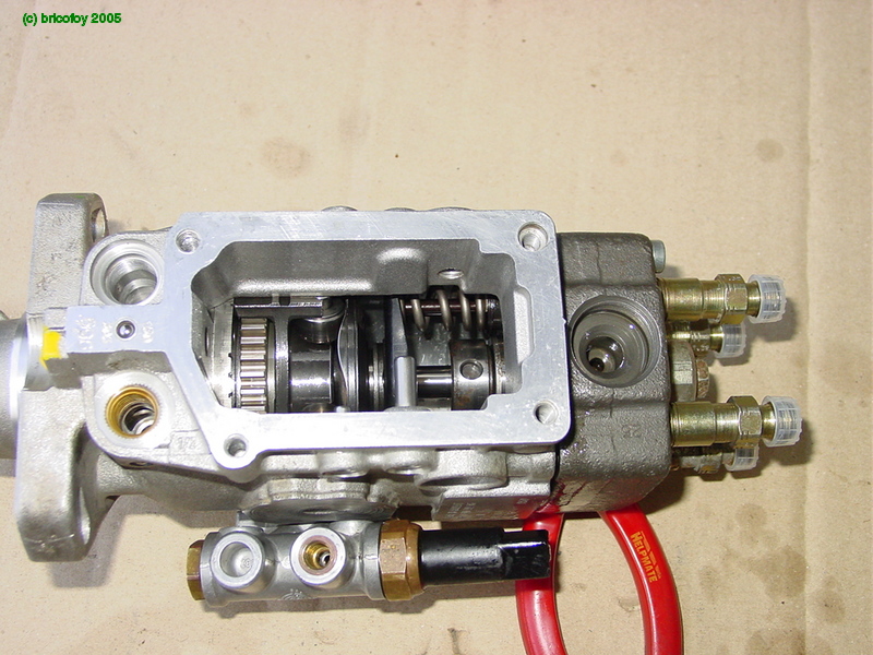
If the cut off solenoid itself really has failed (other than a broken terminal screw, and you could tape a wire to it to maintain contact), the engine can't start. I did think that removing the solenoid and using a magnetic pick up wand to engage the valve may work. However the solenoid valve also seals the rear injector port so removing it would allow fuel to leak out, probably under pressure, so that trick won't work. (See this photo of a disassembled solenoid valve and its location). In this case replacement or modification (see below) of the solenoid is the only answer. This is now on my list of "Things To Do If Desperate".

Fixing the Solenoid

One good suggestion I have seen (thanks to RedZerOne) is a simple modification to a failed solenoid to get the engine going:

"When mine went out two years ago, I gutted it rather than replace it. To do this, remove the solenoid from the VE pump [edit: 15/16 inch spanner] and remove the plunger and the spring from inside the solenoid. Double check in the pump and solenoid that there's no debris and reinstall the solenoid. This will allow the engine to have fuel constantly. It'll operate the same as if you had a working solenoid, the only difference is that in order to shut off the engine, you'll have to manually stall it out. I've been doing this for two years now with no problem."

dsc05410-2011-08-14-08-57.jpg

Remove the spring and plunger and reinstall the solenoid

Photo courtesy http://bricofoy.free.fr/phpwebgallery/

Note, no electrics to the pump are required after this mod and the fuel will be permanently on, which doesn't matter except that the engine won't stop and would have to be stalled. However getting access to the solenoid might require removal or loosening of the top section of the pump, but if you're desperate enough anything goes.

[In fact if you can bump start the Oka after parking on an incline (I'm not sure how easy this is with a diesel, try 2nd or 3rd gear), you wouldn't even need any batteries after this mod to the solenoid. Caution, if you ever try this without batteries, disconnect the alternator first to avoid generating high voltages after the engine starts which could damage any electrical equipment. The batteries normally constrain the voltage to around 14v, even dead ones, but an unloaded alternator can generate up to 100v at very high power and can even be used as a welding supply].

dc993818-2011-08-14-08-57.jpg

This the solenoid location on our injector pump.

It looks inaccessible, but with a 15/16th spanner or shifter it should be possible to remove it.

087f8f82-2011-08-14-08-57.jpg 

The solenoid is on the right, with the top of the pump removed.

It shouldn't be necessary to go this far, I was replacing the throttle shaft seal when this photo was taken.

Friday, 12 August 2011

Electrical/Electronic Mods to our Oka

Being an electronics engineer it was inevitable that I would make and installed lots of electrical/electronic modifications and additions to our Oka.
None of these mods affect the basic functionality of the Oka, in fact there is only one essential electrical item which keeps the engine running or not, which is the fuel cut off solenoid on the injector pump.
As long as you can start the engine, the solenoid wire with 12v applied is the only electrical thing needed to keep it running. See this post for the minimum electrics to start and keep the engine running.
Electrical Mods to our Oka (** indicates my own design/construction)
Mods which relate to Driving
  • Smart alternator regulator for our 120A alternator (Sterling AR12VD)
  • Triple batteries with automatic charge connection and manual paralleling switches**
    • Supercharge Gold MF95D31R (760 CCA) starter battery
    • 2 x Supercharge MRV70 (105 AH, 760 CCA) Allrounder (Starting and Deep Cycle) house batteries
  • Solar panels (200W, 10 x 20W) and multiple battery charge controller**
  • Charge monitoring display system (current and voltage)**
  • Start Lock Out system**
    • Prevents the engine from being started until an enable button is pressed, after the ignition is turned on
    • Fitted with an emergency engine stop button
  • Reversing and forward facing (for seeing over crests) cameras and 9 inch LCD display
  • Wiper delay system**
    • 6 delay periods
    • 1 or 2 wipes per cycle
  • Dashboard electronics**
    • Voltage and charge current meters switchable to each battery (LCD and LED)
    • GPS PSU
    • Turbo Timer
    • Headlight/Step/Vent/Pump "Left On" reminder system
    • Laptop PSU for moving map system**
  • Remote central locking doors**
    • Fitted to all 3 doors, with interlocks so that any internal door handle can lock and unlock all doors**
  • Electric windows on both front doors**
  • Remote switching of fridge dc**
    • Allows fridge to be switched off from cabin when stopped (eg for fuel), to reduce battery load. Normally the fridge runs from 240v ac via the inverter while travelling as it's more efficient than dc, less cable losses. Solar panels provide power when the alternator is not charging
  • Automatic inhibit of Water Pumps**
    • Inhibits pumps when the ignition is ON, to prevent accidental pumping out of water if a pipe leaks or breaks while travelling
  • Diesel Transfer Pump to transfer fuel from rear to side tank
Mods which relate to the Motorhome
  • System switch functions for all rear electrical equipment**
    • Pumps, Lights, Fans
  • Water Level Meters for both main water tanks**
  • Fridge/freezer monitor and alarm system**
    • Display of fridge and freezer temps
    • Over temp and flame failure alarms
    • Indication of energy source (ac, dc or gas)
      •  Note: Fridge is normally powered from ac inverter while travelling, it's more efficient than powering from 12Vdc
  • Fridge Fan to circulate cold air, stops when door is opened**
  • Fridge LED Lights which operate when door is opened**
  • Window Fans to cool us at night (speed controlled from quiet breeze to gale force)**
  • 300W Sine Wave Inverter (Jaycar) with RCD (later removed since it couldn't handle the vibration)
  • Soldering Iron, 24v 60W, temperature controlled, runs from dc-dc converter**
  • Drill battery charger, 24v, microcomputer controlled
    • Runs from same dc-dc converter as soldering iron
  • Computer systems
    • GPS moving map system based on MacBook Air, USB GPS and Oziexplorer running under VirtualBox and XP
    • 17 inch LCD display mounted on engine cover
    • NextG Phone/Modem, (plugs into MacBook), with options of external whip and Yagi antennae
    • 2 x 40W channel HiFi system switchable from radio to computer**
  • Smoke Alarm inhibitor**
    • Prevents activation while cooking. Manual reset or automatic reset after 40 minutes
  • NiCd/NiMH Battery Charger (up to 10 AA and/or AAA batteries at once)
  • Rechargeable Dolphin LED Torch using 8 1/2 W LED's and 6v SLA battery**
  • Dustbuster converted to run from 12v (internal 12v to 6v switching converter)**
  • HF Radio, (Codan 7727 with VKS737 frequencies)
    • Modified to receive ABC and BBC shortwave broadcasts
    • Allows transmit/receive on the 40 meter (7 MHz) amateur band (call sign VK5MDR)**
    • Frequencies can be selected via an external VFO**
    • Allows broader range of emergency frequencies
    • Jenal SC2 microphone fitted to allow direct RFDS connection via Selcall though VKS bases**
    • Tapped whip and 9m Super Rod antennae
  • SW Battery Radio
  • LED Lights**
    • External LED camping lights
    • Internal LED lights
    • Automatic porch/step lights (comes on at dusk when door is opened)
  • Fridge dc low voltage cut off**
  • Roof Vent fan speed control**
  • Evaporative air conditioning controls**
    • Controls small evaporative a/c for use when the engine is off
    • Provides automatic shots of water to keep the evaporator pads damp instead of a continuous supply, to save water. Uses a timer to control a solenoid valve from the pressurised water supply
Future Planned Mods
  • Microcomputer controlled turn indicators/hazard flasher**
    • To accommodate variable loads with future LED lighting systems
    • Static or “Knight rider” type displays
    • Various Left/Right/Hazard “ringtones”
    • Auto volume control (louder with more ambient noise/radio on)
    • Brighter internal flasher LEDs
    • LED and wiring fault detection
    • Auto L/R reset after 15 sec (adjustable)
    • Warning sound, horn or silence on Hazard flasher
    • Hazard flasher can drive rotating lamp and/or alternating L/R or F/R indicators
    • Hazard can flash all lights (Headlights/Stop/Tail/Indicators) alternately to even out battery load
  • Air Conditioning controller**
    • To display internal and external temperatures
    • To control the fans, compressor and front/rear temperature balance

Where We Store Stuff in our Oka

We need to know where we've put things which are not used on a regular basis, like spares and tools, so I keep a list.
Also see this post for photos of other storage areas we've created around our Oka.


Black Hole Box
(This is above the cabin inside our raised roof. It's dark in there, hence the name)

            Awning
            Engine spares (light weight) in plastic box
                        Belts
                        Fuel filter
                        Gloves
                        Hoses
                        Oil filter
                        Radiator repair stuff
                        Safety glasses
                        Thermostat and gaskets (2)
                        Water pump gasket
                        Welding glass
            Diesel pump (small electric water pump)
            Jumper leads (canvas bag)
            Kettle (dirty black campfire kettle)
            Screen room (pop up 2m x 2m x 2m insect proof tent)
            Snorkel and flippers
            Syphon (manual pump operation)

Front PVC Pole Pipe
(This is a 120mm diameter x 2m PVC pipe with screw caps mounted just behind the top of the front bullbar)

            Antenna poles (to extend the NextG Antenna height)
            Awning poles
            Earth stake
            Lengths of tube and strips of aluminium and timber
            Sand Flag pole (mounts on front bullbar in sand dune country. Also useful for hoisting a wire antenna 4m into the air)

Rear Compartment
(The rear compartment is inside the rear hatch, on the floor, but behind a bulkhead so things can't fly forwards in a sudden stop. It's used for heavier tools, equipments and spares)

            4 inch vice
            Air drill and grinding disks
            Heavy tools in steel toolbox
                        Breaker bar
                        Clamps
                        Grease and grease gun (in sealed bag)
                        Hammer
                        Large files
                        Large screw drivers
                        Large spanners/wrenches
                        Jack handle
                        Rubber hammer
                        Tyre levers
                        Wheel brace
            Hose clips
            Jerry cans for fuel, 1 or 2 (not often required, takes up too much space)
            Plastic box of spray chemicals
                        Brake cleaner
                        IPA
                        Silicone grease
                        WD40
            R pins
            Silicon, glue, gasket goo and Loctite
            Snatch strap and Equalisation strap (Winch/Tow Strap and Bow Shackles in external side box)
            Sockets (heavy)
            Spare nuts, bolts, washers and screws
            Square steel container (a 10L campfire oil drum) containing:
                        Brake fluid (1 l)
                        Diff oil (5 l)
                        Engine and transfer box oil (5 l)
                        Hydraulic oil (2 l)
            Suspension bushes/pins
            Tarp
            Welder rods and rod holder
            Gas blow torch

Rear Gate Tool Boxes
(These are boxes built into the skin of the rear gate hatch after removal of the internal steel panel)

            Allen keys
            Clamps, files, tie wraps, tent pegs and raw materials (Ali/Steel/Plastic) (LHS)
            Hex screw drivers
            Saws, chisels and cutting equipment (RHS)
            Small sockets and drivers
            Small spanners
                        A/F and Whitworth
                        Metric
            Bearing puller

Rear Overhead Compartment
(This is one of the internal overhead compartments built into the raised roof. Other compartments are used for domestic storage)

            Box of wire
            Backpacks/rucksacks
            Coats, spare bedding and towels
            Electric terminal kit
            Electronic components
            Shortwave/spare HF Radio
            Spare insect door and window screens
            USB keyboard
            Yagi antenna beam (for NextG phone/modem)

Seat Compartment
(This is a long internal rear compartment built below a seat alongside our kitchen unit)

            Camping chairs
            Hessian sacks
            Hub lift adaptor and
            Sand mats
            Spade (small)
            Table top
            Table leg
            Wheel brace extension bar
            Torque wrench
            Wooden and plastic strips

Shower Recess
(When not used as a shower we store lightweight bulky things in it)

            Hanging rails for damp clothes
            Laundry equipment (line, pegs, soap, washing powder, washing up bowl, sponges, brushes)
            Water pump (electric bilge pump) with pipe and cable/plug
            Padded Milk Crate (used as a seat/step), containing
                         Wine casks
                         Laundry/dirty clothes bags
            Screens for all rear windows to provide heat and light insulation
                         Made from Aircell aluminium bubblepack insulation from Bunnings
                         Fitted with suction caps
            Spray water bottles for very hot weather
            Interlocking rubber mats
            Toilet tent

Side Box
(This is an external steel box mounted behind drivers wheel mudflap)

            Bow shackles (2 x 4.75 tonne)
            Winch extension strap (used as a tow/object removal rope)
            Ropes various

Under/Behind Drivers Seat

            Behind seat
                        Small steel toolbox with hand tools, pliers, small screw drivers, small wrench
                        Emergency Rucksack above toolbox
                        Flashlube and funnel
                        Rubber Gloves (for refuelling)

            In wheel arch box (seldom required items, accessible from under the seat, contents label on top)
                        Bearing locknut socket (4 pronged for Stage 8 Locknuts) and instruction card
                        Bearings (s/h, 1 of each type)
                        Brake pads (1 of each type)
                        Clutch cable (used, but usable for repair of cables)
                        Gas bottle to airline pipe (emergency tyre "air" source)
                        Hi Lift jack extension (for winching)
                        Hi Lift jack overhaul kit
                        Lift Pump and gasket
                        Spring repair kit
                                    (uses spare half leaf mounted under the rear body to repair broken spring eye)
                        Suspension pins and bushes
                        U-Bolt and nuts

Under/Behind Passenger Seat

            Behind seat
                        Airline (small), tyre pressure gauge and air blower tool (in canvas bag, behind seat)
                        Screens for the windscreen and front door windows (same type as for rear windows)
                        Tyre repair kit (behind passenger's seat, under library)

            In wheel arch box (seldom required items, accessible from under the seat, contents label on top)
                        Bearing lock washers and tab bending puller
                        Bearings (new)
                        Brake parts (wedges, springs, bleed nipples)
                        Free wheeling hubs spares
                        Gear ball joint
                        Oil seals
                        Spare  UJ
                        Spare steering rod ends
                        Split pins

Under Rear Bed/Seat
(This compartment is under the seat/bed base and shares its space with a 50 L flexible reserve water tank in a separate compartment)

            Drill bits, drill and battery
            Electrical tool kits
            Small hex screwdriver kit and small fixing screws
            Small Stanley socket set

On the Rear Gate
(The rear gate is for holding one of the spare wheels but we also use it for storing other external items)

            Coiled airline mounted on a 120mm diameter PVC pipe
                        (covered to avoid the effects of sunlight/ultraviolet)
            Levelling wedges
                        (no longer used as we have airbags all round, space for other items)
            Long handled spade (extension handle inside PVC pipe)
            Water hoses (long and short) coiled up inside the spare wheel
            Water tank/tap connectors (inside airline PVC pipe)
            Spare door key (well hidden)

Thursday, 30 June 2011

Fixing the Seat Reclining Mechanism

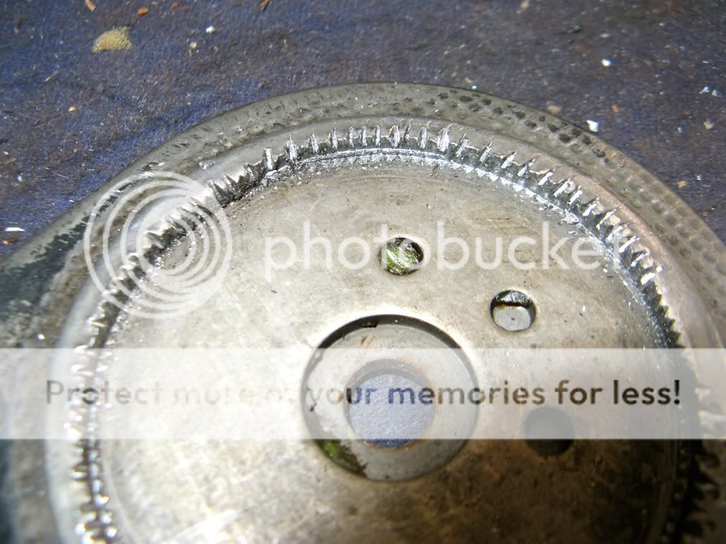
The seat recliner control on my drivers seat is failing and the seat back won't stay up. The teeth on the internal locking ring are worn.

"Moving" part on the left attaches to the seat back, "fixed" part on the right attaches to the seat base.
How it works

The adjuster comprises 2 parts, the "moving" part which is fixed to the back of the seat, and the "fixed" part which is attached to the seat base and on which the adjusting arm is attached (it goes through the centre of the "moving" part).

On the fixed part of the adjuster there are three internal cams with toothed edges which are held by a spring loaded triangular plate against fine teeth on a ring on the moving part, but those teeth have worn flat in places so the seat gives way if I lean backwards. The lever releases the spring allowing the cams to disengage with the ring and the seat back can then move forwards or backwards.

The main spring, which causes the seat back to fold forward when released, is mounted on the opposite side of the seat and is completed independent from the adjuster.

Teeth on the locking ring worn smooth at the most used seat back position
Toothed cams which mesh with the locking ring
I previously turned the cams over so the less worn edge was in use and that worked fine several years but now it's broken again.

Temporary Fix

I've effected a temporary fix to the reclining mechanism.

The mechanism can be disassembled by turning the 4 eccentric locking heads using vice grips until the 2 sections come apart. The adjuster arm will need to be straightened a small amount so that it can slip through the moving part (clamp the mechanism in a vice, slip a piece of pipe over the arm and lever gently).

I reconstituted the ring teeth using a hammer and cold chisel to give the cam teeth something to bite on.

Reconstituted teeth
I fitted shims under the cams to allow them to act on a hitherto unused part of the ring teeth. (Plastic milk cartons are a good source of shim material).

Shims fitted under the toothed cams
I drilled the rings and fitted an "R" pin to lock the seat in position. Actually this was more difficult than anticipated as the outer (moving) ring is peen-hardened and took a lot of drilling. I also drilled a few extra holes on the inner (fixed) ring, which is softer, to accommodate other seat angles. The extra holes only need to be a few mm apart so the same return hole for the "R" pin clip can be used.

I slipped a large washer (not shown) on to the "R" pin to provide something meaty to pull on and when the seat needs to be tilted forwards, it's very quick to pull out the pin, just like a grenade.

An "R" Pin to hold the seat back in position
The "R" pin is a belt and braces solution which will prevent a sudden collapse occurring on an outback trip, but even without it you can usually jam something behind the seat, as we did when the problem first happened (on the west coast of Tassie).

Of course this fix doesn't take the place of a properly functioning mechanism but it works fine for the time being.

The Cause

I suspect the damage was caused in the 1/2 million km that our Oka had done before we bought it, especially if the lever wasn't fully released before reclining the seat, allowing the teeth to grind over each other. It first failed several years ago and we do use the mechanisms quite often to provide access behind the seat but without abusing them.

Dirt build up probably doesn't help and once the teeth don't mesh fully, they start slipping, which will only escalate the wear problem.

Saturday, 25 June 2011

Under Wheel-Arch Storage Boxes

Our Oka is a bus model converted to a motorhome so there is limited internal space for storage of heavy spares, except in the rear hatch area. However that area is behind the rear wheels and, with a heavy spare wheel gate mounted across the rear, results in a lopsided (lop-fronted?) front/back weight distribution.

So I'm always on the look out for additional external storage areas on our Oka, especially low down (for heavy objects), to relocate weight from the rear to the front/middle and to free up rear space.


For sometime now I've been eyeing up the cavernous space under the front wheel arches. We previously fitted water tanks under the wheel arches of an old Land Rover for a round the world trip so I know it works, if you leave sufficient space for wheel movement.

443636cb-2011-06-25-09-17.jpg

The huge space under the front wheel arches was just begging to be used

Further on I've describe how I made use of this space with some simple boxes, accessed from under the seats, but first, here are some of the external storage spaces we've already used.

Spaces Already Used

Making use of the wheel arch space came only after we've already used pretty much all the obvious spaces on the Oka:

  • the area behind and alongside the fuels tanks for:

443636cb-2011-06-25-09-17.jpg

10 litre removable waste water tank and 4.5 kg gas bottles

    • the space outside the RHS fuel tank for a thin water tank (made from 90mm PVC pipe to hold 25l of shower water),
  • 443636cb-2011-06-25-09-17.jpg
  • 25 litre "snake tank". People called it a snake tank, so Janet painted a serpent on it.
  • the space behind and below the passenger seat (directly opposite the air filter) for:

443636cb-2011-06-25-09-17.jpg

A 3rd battery. There is still a big unused space above the battery.

  • the spaces under the rear bull bars for:

443636cb-2011-06-25-09-17.jpg

A reserve gas bottle on the LHS

443636cb-2011-06-25-09-17.jpg

A frame for a jack and 2 axles stands on the RHS (empty in this photo)

  • the space behind the front mud flaps for:

443636cb-2011-06-25-09-17.jpg

Water containers and air compressor controls on the LHS

443636cb-2011-06-25-09-17.jpg

A box for recovery gear on the RHS (winch strap, bow shackles, rope etc)

  • the space below the centre of the floor for 2 water pumps, gas regulator, and gas and water tank change over taps (accessed via a floor hatch).
  • 443636cb-2011-06-25-09-17.jpg

    Internal floor hatch

    • on the front bullbar a Hi Lift jack is stored, together with 2m of 125mm PVC pipe used to hold awning poles, sand flag pole, antenna poles,

    443636cb-2011-06-25-09-17.jpg

    Hi Lift jack and pole storage pipe on front bullbar

    • on the rear wheel ladder we have a coiled airline pipe, water hoses, a pair of levelling wedges and a long handled spade,

    443636cb-2011-06-25-09-17.jpg

    The rear gate is full up with stuff

    • the rear hatch internal space is modified to use as 4 separate tool boxes, with the top as a work bench.

    443636cb-2011-06-25-09-17.jpg

    Rear hatch tool box mods

    443636cb-2011-06-25-09-17.jpg

    Rear hatch in use as a tool box and work bench

    Front Wheel Arch Space

    The space between the top of the front tyre and the bottom of the floor plate is at least 200mm at the absolute maximum possible travel of the suspension (with 285 x 19.5 inch tyres), so I have fitted a 125mm deep box under each wheel arch, which should allow adequate worst case clearance.

    443636cb-2011-06-25-09-17.jpg

    Storage box mounted under the drivers seat. It would be better if they fitted right across the available space.

    The shock absorber has room to move and its bolt is still accessible.

    I did have to identify possible strong points for mounting the boxes and watch for the location of, and access to the shock absorber mounts. These limit the available width of the boxes to about 200mm, without intruding on the wheel spat area, or making the mounting/sealing arrangements unnecessarily complex.

    I happened to have a long aluminium box originally designed to hold 2 jerry cans on a roof rack, so I cut it in half, blocked up the open ends and fitted some mounting angles to the tops. At 500mm long, they are not quite as long as I would have liked, but beggars and choosers etc. It would be better if the boxes stretched the full 700mm right across the wheel arch to reduce the number of cavities that mud, water and dust can penetrate.

    It would be an easy job to fabricate or adapt some simple boxes to fit. I did initially look at adapting some small steel tool boxes or army surplus "ammunition" type boxes before remembering my nice long aluminium box. Plastic boxes should be avoided however, since they will be exposed to high speed rocks, sand and water thrown up by the wheels, not to mention shock and vibration.

    443636cb-2011-06-25-09-17.jpg

    A long aluminium box cut into 2.

    Access to the Boxes

    Access is via a simple hatch door under the seat as they are intended for storage of rarely used items, such as wheel bearings, UJ's etc. You wouldn't want to store often used items here since removing the seat is a bit of a pain, but a side access plate could be fitted, bearing in mind it will be exposed to the elements and wheel driven sand, water, rocks etc., and it would need to be very secure.

    443636cb-2011-06-25-09-17.jpg

    Access hatch under the seat.

    443636cb-2011-06-25-09-17.jpg

    Simple slide-in hatch covers, held in place by M6 captive nuts.

    Mounting the Boxes

    The seat frames provide suitable strong points for mounting the boxes as you don't want them to fall off, scattering your spares along the track. However, the bottom of the front base of the seat sits quite close to the frame so thin headed bolts (countersink or no washers) will be required or the seat fixing won't locate correctly. I used M8 bolts.

    443636cb-2011-06-25-09-17.jpg

    Hatch cover in place. Note the mounting bolts on the seat frame. The 2 other bolts are close to the door frame. 

    While preparing the wheel arch I discovered (actually re-discovered) some rust holes in the floor plate around the seat frame. These needed to be treated before mounting the boxes.

    I painted the boxes with under-seal for protection, and fitted thick foam sealing strips around the top surface (since the bottom of the floor pan is not flat) to reduce the ingress of the aforementioned mud, water and dust. I am always torn between fully sealing a container to keep out water and dust, or accepting the inevitability of leaks and fitting drain plugs. For these boxes I've attempted both. I've sealed them as best I can but provided blanking plugs on the bottom so that any water/dust that does penetrate can be more easily removed.

    The Contents

    The boxes have a volume of around 10 litres each, which doesn't sound much, but it's surprising how many spares you can fit into such a space.


    443636cb-2011-06-25-09-17.jpg

    The access hatch is around 150 mm square, but could be longer.

    The kinds of things we store in these boxes are:

    • Wheel bearings and cups (1 of each type), lock washers and tab bending puller
    • Bearing locknut socket (2 1/2 inch box spanner)
    • Freewheeling hub spares (the plastic bits inside can break)
    • Gear ball joint
    • Oil seals (rear hub)
    • Spare UJ
    • Brake pads (1 of each type), calliper springs, screws and clips
    • Clutch cable (old but suitable for repairing clutch, throttle and handbrake cables)
    • Gas bottle to airline pipe (emergency "air" supply)
    • Hi Lift jack extension (for winching)
    • Hi Lift jack overhaul kit (actually the old bits after overhaul)
    • Lift Pump and gasket
    • Suspension pins and bushes
    • U-Bolt and nuts

    I wrapped the heavy items in bubble wrap to protect them both from vibration and the possiblilty of water damage.

    The result is that I have relocated more than 10kg of weight from our rear compartment to a lower point, nearer the front, and I've also freed up 20 litres of space in the rear.

    Sunday, 5 June 2011

    Rear Towing Points on an Oka

    If you have rear bullbars on your Oka, but no bar (we used the rear space for extra fuel tanks), rear ing points can be easily added if you have built in reinforced high lift jack points. This applies mostly to full body models.

    Drill a 22mm hole (or whatever size fits your D or Bow shackle pin snugly), just behind the high lift jack points on the side plate of the bullbar frame. The hole should be low enough so the shackle can be lifted to at least the horizontal position.

    IMG_5768-2011-06-5-23-59.JPG

    22mm holes in the bullbar side plate

    The D or Bow shackle will fit neatly through the jacking point and provide strong ing points on either side of the Oka.

    IMG_5765-2011-06-5-23-59.JPG

    IMG_5766-2011-06-5-23-59.JPG

    Bow shackle located on the bullbar

    The bullbar side plate is 8mm steel and is bolted directly to the Oka chassis using the same 16mm bolts provided for holding a bar. It's the equivalent of the points built into the front bullbar and probably stronger. It's also the primary member used by the high lift jack in raising the vehicle.

    Using D or Bow shackles on both sides and an equalisation strap (or a tree trunk protector), the stresses can be shared and equalised between each bullbar when the Oka is being towed backwards, or while pulling another vehicle or object off a track.

    Notes:

    1) Shackles with at least a 4.75 Tonne rating are recommended (equivalent to 10,500 lbs). If you need more than this you probably need a crane not a truck.

    2) A webbing strap will fit a Bow shackle better than a D shackle.

    3) A steel plate or large washers with 22 mm holes could be welded to the side plate to stabilise the action of the shackle if required, or packing pieces can be added to the shackle pin as shown below.

    shackleloads-2011-06-5-23-59.jpg

    4) Don't leave the shackles attached whilst driving, the pins will vibrate loose and the shackle will drop off.

    5) Bolt-on hooks area available in 4WD shops but they are not as reliable as as D or Bow shackles since you are dependent on the strength of a hook (not a closed steel loop) and the integrity of 2 or 4 small bolts. In any case I couldn't find anywhere suitable to mount them.

    If you have to use bolt on tow points, use something like these (from TJM), ie a closed steel loop with at least 3 high tensile fixing bolts (and somewhere substantial to mount them).

    PastedGraphic-2011-06-5-23-59.png

    Not this type:

    PastedGraphic1-2011-06-5-23-59.png

    Thursday, 19 May 2011

    Fitting Airbags to an Oka

    Surprisingly, a search of the Oka Owners Group forum revealed only five references to fitment of airbags to an Oka, (and one of those was mine), plus an article by Peter Furlong from several years ago.

    I'm aware of at least 6 Oka's with airbags fitted but I'm sure many other people are toying with the idea.

    In the May 2011 issue of the CMCA magazine The Wanderer is an article by Collyn Rivers on "Airbag Characteristics" which makes interesting reading. In an earlier article (Feb 2011) he cautioned that airbags should never be fitted only to either the front or rear of a towing vehicle, citing potential jack-knifing of caravans. (Note you may need to be a CMCA member to access articles from The Wanderer).

    Having recently fitted airbags to both the front and rear of our Oka, I was somewhat relieved to read Collyn's conclusion that "there is no reason at all not to use air bags if you wish. They are first rate engineering products, but specifying them correctly requires considerable skill and expertise".

    In the latest article he explains in more detail implications of adding airbags to a suspension system. He also refers readers to an article on his website (Vehicle Dynamics) which discusses generally how a vehicle behaves on the road. Although much of the emphasis relates to towing and caravan applications these articles are worth reading before embarking on any changes to an Oka suspension.


    Why Fit Airbags?

    I wanted to use airbags for 3 main reasons:

    • to shift some (roughly half) of the load off the springs and suspension pins and thus improve their reliability,
    • to provide some suspension levelling for differing loads, road cambers and to compensate for spring wear (sag),
    • to soften the ride over rough tracks and corrugations, and
    •  since we live in the Oka while traveling, being able to level the vehicle at night was an additional side benefit.

    Fitting airbags to the rear suspension in 2010 was easier than the front and I'm glad I tackled that end first. On a 14,000 km trip up to the Tip of Cape York they performed well, allowing load levelling and raising the rear as necessary. Passengers in the rear reported a very smooth ride even over quite severe corrugations. It was a very different story in the front however, sitting directly over the wheels, with quite stiff front springs and heavy duty (Ralph) shock absorbers, the ride was shattering over any significant corrugations, and it was that which lead us to install airbags on the front this year, in an attempt to provide a smoother ride as well as the other levelling capabilities.

    Individual airbag pneumatic controls is required to get the most benefit from these functions.

    Airbag Research

    I did as much research as is practical into airbag selection (also called air springs) and reviewed other people's installations. The model we fitted is that recommended for the Oka by the Firestone Airbag importer, The Airbag Man, their part number AB0051. This is a Firestone model 1T14C-1, which defines a family of reversible sleeve air springs. The Firestone Assembly Order Number is W01-358-5311, which defines the specific characteristics of this variant (and there are hundreds of variants). This is also the number to use for an internet search.

    The metric datasheet can be found here and the imperial version here. A brief explanation of how an air spring works is here and a full Engineering Design Guide can be found here. There are other manufacturers of airbags, notable Goodyear, but most applications seem to use Firestone.

    For some insight on airbag failure modes see this Goodyear document and scroll down to page 168. Over-extension, chemicals, corrosion, impact and abrasion are the most common causes of failure (can there be many others?). This site shows the failure modes for airbags fitted to a Range Rover.

    IMG_5719-2011-05-19-16-10.JPG

    Driver side front airbag fitted. This was the trickiest due to the studs on the diff housing.

    Airbag Calculations

    The W01-358-5311 model has an internal buffer, so it can be used to replace the standard Oka Aeon rubber bump stops, (although in normal operation the internal buffer would hardly get used so it's prime function would be to protect the airbag from damage though over-compression) and has a design height of 255-260 mm which is just what an Oka needs (roughly the space between the top of spring and the chassis bump stop mount). This model can be used from about 160 mm to 320mm operating height but at 260 mm, it's in the design centre of both it's height range and air pressure range of about 3 to 5 Bar (40-60psi), which is load dependent.

    In a very simplistic calculation to verify this assumption, for an Oka at 5500kg, each spring carries roughly 1000-1200kg (allowing for the unsprung axle/spring/wheel weight), with probably more at the rear than the front. To support half this load requires the airbag to support about 500-600kg at it's normal operating height. From the Firestone datasheet, at this load and 260mm height, the internal air pressure required is around 3-4 Bar (40-50 psi) which is in the centre of its operating range of .7 to 7 Bar (10-100 PSI). Collyn Rivers in his article notes that the best airbag operation (soft ride with impact absorption) is over the lower 40% or so of it's pressure range, so on that basis we are about right.

    Note of caution: at maximum pressure and/or operating height, these airbags could spread the spring/chassis separation distance to a point which might over-extend the length of a shock absorber. This could lead to a mechanical failure somewhere. It's unlikely to occur in practice if the vehicle height is kept within normal bounds but I suggest keeping airbag pressures down to 20-30 psi when the Oka is lightly loaded (eg between trips) to avoid this. Taking weight off an airbag quickly allows it's height to increase unless the air pressure is also reduced (Boyles Law).

    Source of Supply

    You can buy these airbags from The Airbag Man, or their distributors (eg Air Springs SA , which is what we did for the first 2), or from any number of US on-line stores eg TruckSpring.com (which where went for the last 2 at a considerable saving (more than 50%, even after the addition of freight) or SDTruckSprings.

    Genuine Firestone pneumatic controls and gauges are also available from the same US suppliers but we found a local supplier Air Ride Suspension in Sydney who was almost as competitive, so we supported them. They can also supply the air pipe and push-fit connectors (which are very quick and effective).

    Control_2wP_Rear_sml-2011-05-19-16-10.jpg

    ControlPneu_2way_sml-2011-05-19-16-10.jpg

    A dual pneumatic control panel. Two are needed for individual control of 4 airbags.

    There are individual air switches and a dual needle pressure gauge (white and yellow needles).

    Planning the Project

    Fitting airbags is not a trivial task as it requires a fair amount of steel fabrication and assembly, to design and manufacture the top and bottom plates to support the airbags and to meet the physical peculiarities of the Oka, and to align and attach them securely to the springs and chassis. For a tough, off road vehicle, this certainly requires a lot more than "just bolt the top and bottom plates on" concept shown in the Firestone installation video.

    Neither is it a cheap exercise, an airbag will cost from $200-400 each, depending on the source (US/Aust), and a dual control panels are $150-200 each, so the total for 4 airbags with individual controls is around $1500. It is possible to pay more, by fitting an all-electric system of electrically controlled valves for each airbag. This allows the system to be controlled by electrical, rather than pneumatic switches, or an automated electronic levelling system, like a Winnebago.

    Much useful practical experience was gained from David Hallandal's airbag installation, and I appreciate his help and assistance with this, and I also located several web photos of other installations to analyse.

    Top and bottom steel plates must be mounted to the Oka to provide flat platforms for the airbag to operate between, and be attached to. The top plate is attached to the chassis via the bump stop bracket after the Aeon rubber buffer has been removed. The bottom plate is attached to the spring clamp.

    Fitting the rear airbags is the least challenging and there are several ways of supporting the top and bottom plates. Apart from ensuring reasonable alignment of the top and bottom plates (and Firestone claim that they are quite tolerant to misalignment of up to an inch either way), the challenge is primarily the design of the mountings so that they can actually be assembled on the vehicle.

    The airbag piston (the large aluminium casting supporting the rubber bag) is sandwiched between the airbag and bottom plate by a single centre bolt into the airbag. This is fitted up from underneath the bottom plate and needs to be a countersunk head bolt since it will be located on top of the spring clamp. The piston has no fixings of its own.

    The fixings for the top of the airbag comprise 2 captive tapped holes and an air inlet hole. The top plate needs to be designed so that the bolt holes are accessible for insertion of the bolts when the top plate itself is fitted to the bump stop bracket, while allowing the air inlet connection to be accessible for connection of the air pipe.

    A 25mm spacer is also required so that the top plate clears the chassis frame, and a countersunk bolt is needed to fix the top plate to the bump stop bracket since its head will be located directly above the airbag.

    Here are a few Installation Techtips transcribed from the Firestone Web site. Click on the headings to go to the Firestone website.

    Here are a few quick tips to make the installation of your air helper springs and air accessories correct and ensure proper operation of your system.

    Air Spring Alignment

    Air Spring alignment is important to the operation of your air helper spring kit. Upon installation, visually align the air spring. There is no need to use a level or other measuring device because the air springs are very forgiving, if it's off a fraction you should be fine. Most kits allow for movement of the upper and lower brackets to assist in making the air spring vertical. Position the brackets so the upper and lower brackets are parallel. The most important item to consider when placing the air spring is design height. As long as the proper design height is maintained and the air spring is as vertical as possible your kit will provide you with years of service.

    Push-to-Connect Fittings


    Firestone's push-to-connect fittings are extremely easy to use. Once the length of air line has been selected to span the distance from the air springs to the inflation valves simply use a sharp knife to cut the air line as square as possible (DO NOT use hand cutters or other devices that may deform the end of the air line) then push the air line into the fitting as far as possible. That's all there is to it.

    Air Spring Clearance


    After installing your air helper spring kit make sure you have at least 1/2" of clearance around the entire air spring. A good rule of thumb is to use the thickness of your hand and feel around the entire air spring if you hand comes in contact with an object on the vehicle you may have a problem. If the object can be moved relocate it if it cannot contact Firestone for further assistance.

    Mechanical Design Summary

    I used 5mm steel plate for the top and bottom plates although you could use 6mm plate or buy universal plates from airbag suppliers already drilled. They would still need mounting arrangements fitted though, as there are no plates commercially available which directly suit the Oka.

    With the top and bottom plates manufactured, the basic sequence of assembly is:

    Attach the top plate to the bump stop bracket using a countersunk bolt, and aligning the airbag top fixing holes,

    Fit the air connection to the top of the airbag (use a swivelling 90º push-fit connector),

    Attach the airbag to the top plate using bolts down though the top plate into the 2 captive nuts (after fiddling the air connection though its hole),

    Attach the bottom plate to the airbag using a countersunk bolt up though the piston, aligning it radially so it fits the chosen spring clamp arrangements,

    Ensure the air connector is not blocked off and pull the airbag down, allowing it to expand, (but DON'T use air pressure, you could crush fingers or break something) and bolt the bottom plate to the spring clamp,

    Fit the air pipe and connect up the air supply and controls.

    It sounds easy but the devil is, as always, in the detail.

    Rear Airbag Development

    The bottom plate is probably the easiest to start with.

    Assuming the U-bolts and spring centre bolt don't protrude above the level of the spring clamp (if they do they will need to be cut off or clearance holes cut in the plate), the plate can be designed to rest on the centre of the spring clamp with supporting out-riggers welded on which rest on the wings of the spring clamp. The plate can be held on by bolts (high tensile to survive vibration stress) down though the wings of the spring clamp (the bolts need to be positioned carefully so their heads don't foul the outer edge of the airbag piston) or up though the wings of the spring clamp into tapped holes on the bottom plate (be careful of the depth). For bolts hidden under the piston, assuming they don't foul the insides of the piston, their heads could be welded on to the bottom plate.

    4ef1f1f5-2011-05-19-16-10.jpg

    Rear airbag bottom plate, viewed from underneath.

    The horizontal bars rest on the spring clamp wings.

    Other fixing methods could also be devised by attaching brackets to the spring clamp. The Firestone suggestion of using clamps around the spring pack is not desirable as it can bring unfortunate results.

    876a43d3-2011-05-19-16-10.jpg

    Clamps around the spring pack can slip.

    This photo of NT001 is from the "Suzi and Rudi on Tour" website.

    The airbag was apparently undamaged but the mounting arrangements had to be redesigned.

    Note that access to the U-bolt nuts will probably not be possible after fitting the airbags (although you might be able to provide access holes though the plates for some, but not all of them), so ensure they are fully tightened before doing any design or assembly so things can't move. Subsequent checking of U-bolt torque will necessitate jacking up the chassis, releasing the air pressure, unbolting of the bottom plates and raising the airbags out of the way to provide access to the nuts. The airbags don't have to be removed completely.

    The top plate needs to be mounted to the bump stop bracket via a 25mm spacer so that it clears the bottom of the chassis rail. A long countersunk bolt can be used for this and I chose to weld its head on to the plate since it won't be accessible once the airbag is bolted on, but that's not essential. Alternatively, a bolt could be inserted downwards through the bump stop mounting bracket into a tapped hole in the top plate (be careful of its depth). Holes will be needed to attach the airbag to the plate and will have to be arranged so that the air inlet connection is accessible. One hole will probably go through the bump stop bracket, which is a good thing as it prevents the plate rotating in service.

    d5a25cff-2011-05-19-16-10.jpg

    My top plate with the spacer block and completely OTT strengthening ribs

    For the 25 mm spacer, I welded a steel box to the top of the plate. A couple of thick steel blocks would do but are heavy, like the cylindrical block removed from above the bump stop rubber. I have seen photos of round cylinders or square tube used for this purpose (see below), which might simplify the design, but I preferred a more substantial arrangement. I probably went overboard by welding strengthening ribs to the top of plate as well but this can cause the plate to warp.

    30dd4731-2011-05-19-16-10.jpg

    Rear airbag top plate trial fit.

    The square spacer block is needed to clear the chassis rail and the round spacer is because the bolt was too long.

    3997bb07-2011-05-19-16-10.jpg

    Roughly shaped rear top plate, view from below

    Alternative rear top plate spacer ideas:

    d25a3d4f-2011-05-19-16-10.jpg


    96b1582a-2011-05-19-16-10.jpg


    Alignment of Plates

    Alignment of the top and bottom plates can be problematic. The location of the airbag is governed mostly by the position of the top fixing holes which are in turn constrained by the chassis rail and bump stop bracket, but it should be inboard rather than outboard to maintain adequate clearance from the tyre.

    250ccdf4-2011-05-19-16-10.jpg

    Rear airbag trial fit

    Using cardboard templates, the approximate centre point of the top of the airbag can be determined. With the spring/chassis spacing at the normal distance of around 260mm, drop an approximate vertical from the centre of the top plate to the spring clamp. This will determine the centre fixing hole for the piston but a misalignment of 1 or 2 cm won't affect airbag operation, after all, springs are flexible items and move around and expand and contract all the time when driving.

    The centre fixing bolt should be as close as practical to the longitudinal centre of the spring clamp (I don't like the idea of mounting the airbag to the spring itself) but is unlikely to be central laterally (due to the fixing hole problems) and doesn't need to be. My rule of thumb is that the centre of the airbag should be no further inboard than the edge of the spring. If the airbag is outboard there is a risk of it being abraded by a tyre at full axle articulation.

    Front Airbag Development

    These are slightly more challenging than the rear due to the proximity of engine components, shock absorbers and steering movement of the tyre. Also, on the drivers side, the stud fixings from the spring clamp to the diff housing get in the way.

    [Previously, we also had fitted an additional full length #3 spring leaf to all the springs to provide extra support to the spring eyes and suspension pins and this was in part the cause of our rough ride, and also raised the front of the Oka too much. So before embarking on the front airbag design, I removed leaf #4 from the springs (retaining the added #3 support leaf), to soften and lower them so that about half the load could be taken on the airbag at its preferred height. This was a challenging, finger risking exercise in itself but not directly related to the fitting of airbags.]

    As for the rear, if the U-bolts or spring centre bolts protrude above the top of the spring clamp they will need to be cut off and/or clearance holes cut on the bottom plates. However this can't be done for the 2 studs into the diff housing. The thread length could be shortened, or the studs replaced by bolts, but they will still protrude above the level of the spring clamp. Fortunately, the hollow area inside the airbag piston allows it to be located over the studs with adequate clearance, and that will dictate the location of the airbag on the drivers side. When cutting clearance holes in the bottom plate for the studs and nuts, note that the stud spacing is different to the U-bolt spacing.

    Apart from that, the bottom plate design can be similar to the rear airbags, except that mounting arrangements will necessitate brackets being welded or bolted on to the spring clamps to allow the plate to be attached.

    b70f65cc-2011-05-19-16-10.jpg

    Drivers side airbag. The diff studs fit under the piston and brackets were welded on to the spring clamps to allow fixing of the bottom plate.

    At the front, the top plates are actually a bit easier than the rears, since the bump stop brackets are lower than the chassis rail so no spacer is required. However, the location of the airbag fixing holes and air inlet connection will still require the same degree of design experimentation. The tapped bump stop M12 slug can be used to hold the top plate on via a countersunk bolt but I also welded a bracket on top of the top plate and used a bolt though the inner side of the bump stop bracket for additional stability. This also prevents the plate from rotating in service. Support plates could also be welded to the chassis or bump stop bracket if desired. Note, the 2 bump stop brackets are slightly different in design, the drivers side bracket is wider. (I suspect this was due to the bump stop having to be moved outwards to clear the diff studs).

    In my case, on the LHS, I have an air compressor mounted on the engine mount so I had to ensure that it could not come into contact with the airbag. So the LHS airbag is more outboard than the RHS, but still will not come close to the tyre.

    98903846-2011-05-19-16-10.jpg

    Left side front airbag fitted in between the tyre and compressor

    Pneumatic Controls

    Once the mechanical manufacture and fitting is done (which took over a week of full time work for each of the rear and front systems), the air system can be connected. Obviously a permanent source of air pressure is required but airbags don't require a huge volume of air like tyres do, only pressure up to 100 psi (although in reality 60-70 psi is more than adequate), so an electric compressor would be satisfactory.

    For maximum flexibility, individual air controls are preferable but the front and rear pairs (or indeed the left and right pairs) could be commoned up but you would loose the ability for selective levelling. Since I fitted airbags in 2 stages, I bought 2 dual control panels at different times which I mounted either side of the steering column and that works out quite well. However a quad controller is also available but would require more space to fit.

    cca1dd38-2011-05-19-16-10.jpg

    2 sets of dual controls mounted either side of the steering column but there are 5, 1/4 inch air pipes to run though the floor

    Running the air pipes to the individual airbags around the chassis, plus one to the compressor, is a bit of a pain. They must be fixed (with tie-wraps) so that they are protected from wear and impact (ie above or behind chassis rails like brake pipes), as the sudden deflation of an airbag could cause handling problems.

    I fitted a check valve and tap to the airbag air supply so that the airbag system can be isolated from my main air system and be protected from any compressor failure or maintenance activities. I didn't want sudden suspension changes to occur while working on the compressor system, although this is highly unlikely since the control panel switches prevent release of air from the airbags. A small air tank could also be fitted as a reservoir to maintain the airbag supply.

    I leak tested all the joints with soapy water and once fitted, the quick push-fit connectors have never leaked. The control system works well although manipulating 4 controls is a bit of a handful. I connected the rear left and right airbags to the LHS control panel and the front left and right airbags to the RHS control panel. The gauges have dual needles, one white and one yellow. I connected them so that "White is Right" so I can remember which is which.

    Potential Problems

    When fitting the rear airbags I was initially concerned whether the tyres could ever impact the airbags at maximum axle articulation so I fitted some protective plates, partly to tell if there were any wear points and also to protect the airbag if there was. After the Cape York trip there had been no contact at all so the plates are now redundant. But I did have to re-route the exhaust system so that it was well away from the airbag and fitted a heat deflector plate as well.


    If an airbag does get punctured (rather than worn away though abrasion), it might be fixable temporarily using a tyre plug.

    8edb1ae1-2011-05-19-16-10.jpg

    Right side rear airbag with protective plates and heat shield

    Summary

    Fitting airbags has been a long but interesting task. The rear airbags worked well over 14,000 km but I have yet to test the front airbags over any rough tracks. A question still remains over whether stronger or softer shock absorbers work best with airbags and I'll be testing both types on the next trip.

    I'm hoping that my calculations and assumptions are correct and that we'll get some significant ride benefit from them, plus improved suspension reliability, as well as overnight motorhome levelling.